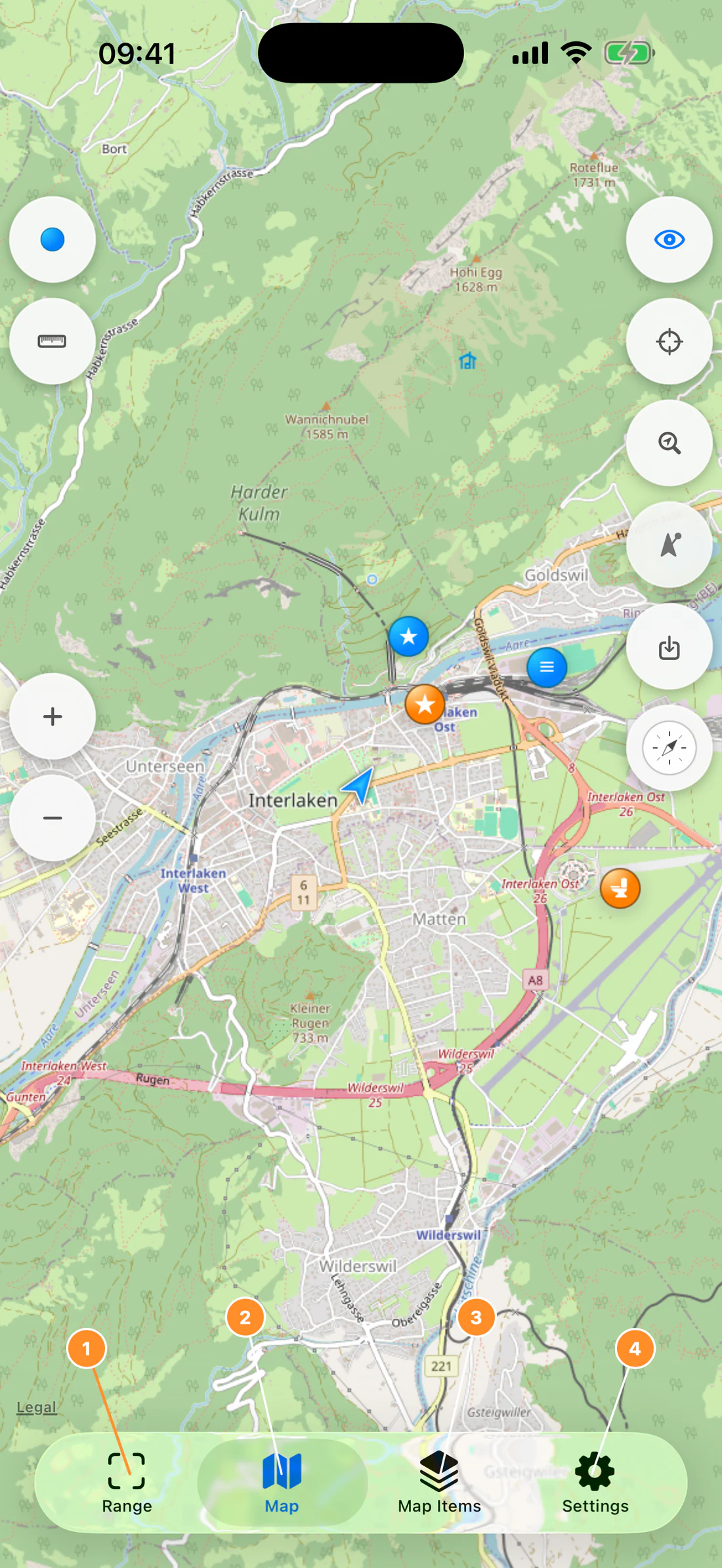
RangeFinder combines camera instruments, map measurements, offline maps,
waypoints, a map compass, and field astronomy in one app. This guide explains
how to choose the right instrument, obtain a result, assess its quality, save
the evidence, and continue working when a sensor or network is unavailable.
Important: RangeFinder is a field measurement aid. Results can be
affected by target dimensions, camera alignment, calibration, reflective
surfaces, sensor quality, device motion, location accuracy, and map data.
Confirm important measurements with an independent instrument.
Start with the task
I want to…
Start here
What RangeFinder uses
Estimate the distance to an object of known height
Known Size, Waypoints, Angle, Angle Survey, maps, offline areas, map
measurements, Map Compass, and Astronomy are designed for supported iPhones and
iPads. LiDAR and Surface appear in the Range mode selector only when compatible
LiDAR hardware is available. If LiDAR is absent, Range shows Known Size and
Waypoints; the app does not display a nonfunctional LiDAR or Surface mode.
Camera, location, heading, motion, photo-library, and microphone behavior must
be tested on a physical device. Simulator layouts are useful for learning the
controls, but Simulator does not provide a real camera, LiDAR stream, or normal
field sensor evidence.
Measurement result language
The app deliberately distinguishes:
Acquiring — the instrument does not yet have enough valid data.
Estimate — the result was calculated from camera geometry and user input.
Stable — supported direct or surface sampling has reached a usable state.
Medium quality / Use with caution — a result exists but conditions reduce
confidence.
Unavailable — a requirement is missing or the capture session cannot
provide a valid result.
Do not record the placeholder dash as a measurement. Wait for a numeric result
and read its status and guidance together.
Support
For help that is not resolved by the troubleshooting chapter, contact
support2026@lifewaresolutions.com. Include the app version, iOS/iPadOS
version, device model, selected instrument, and the exact message shown. Never
send API keys or private location/media unless you deliberately choose to share
them.
Quick Start
Use this chapter to choose an instrument and prepare a trustworthy first
measurement.
1. Complete permissions at the right time
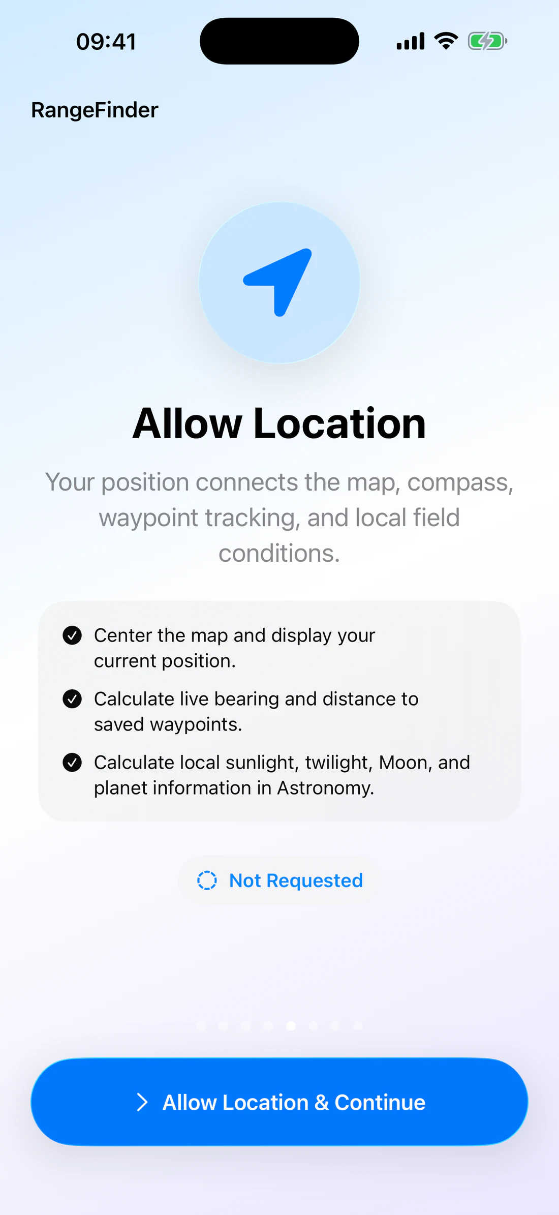
On first launch, RangeFinder explains each permission on its own onboarding
page. The system request should appear only when that page is selected and you
press its primary action.
Location supports the current coordinate, map position, waypoint distance,
camera waypoint projection, Map Compass, and location-based Astronomy.
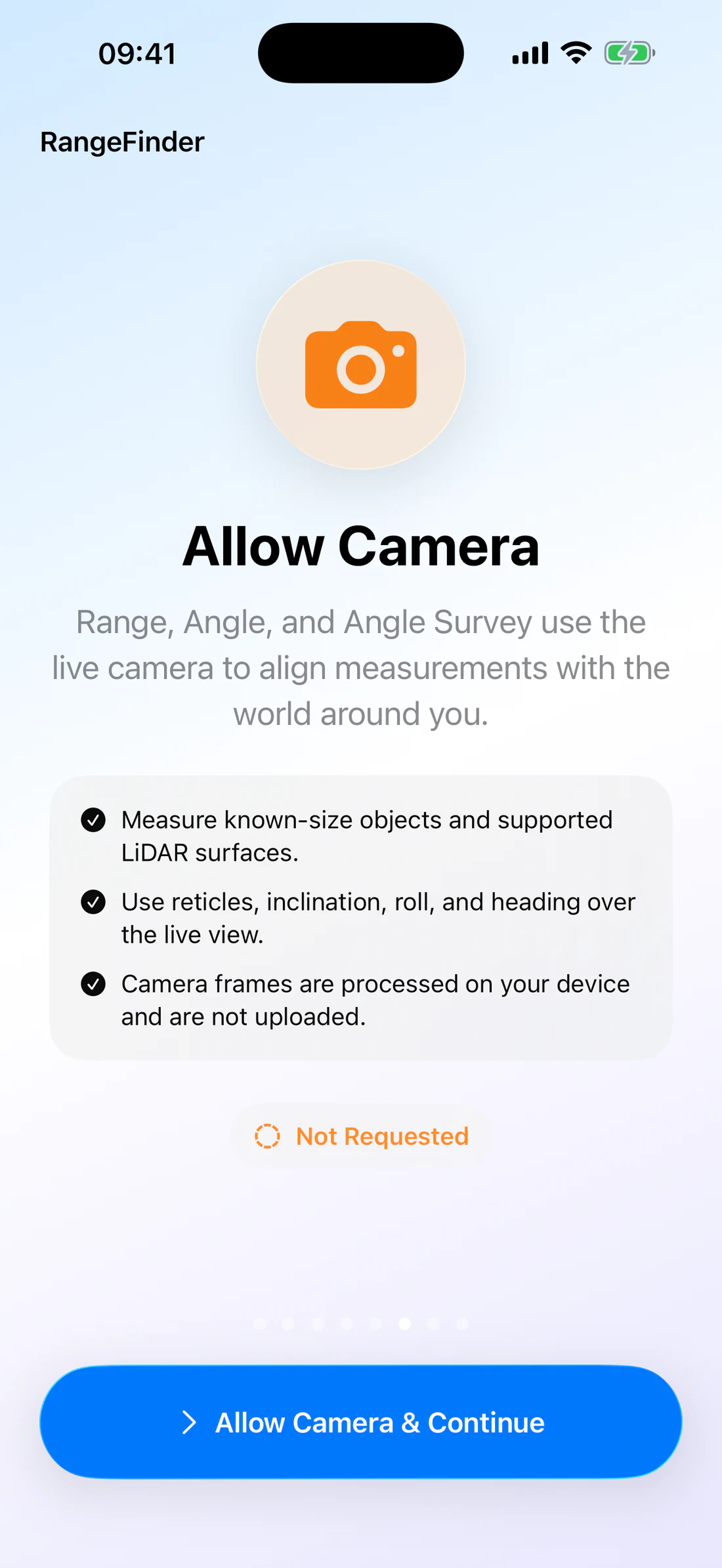
Camera supports Range, Angle, Angle Survey, instrument photos, and
photo-based workflows.
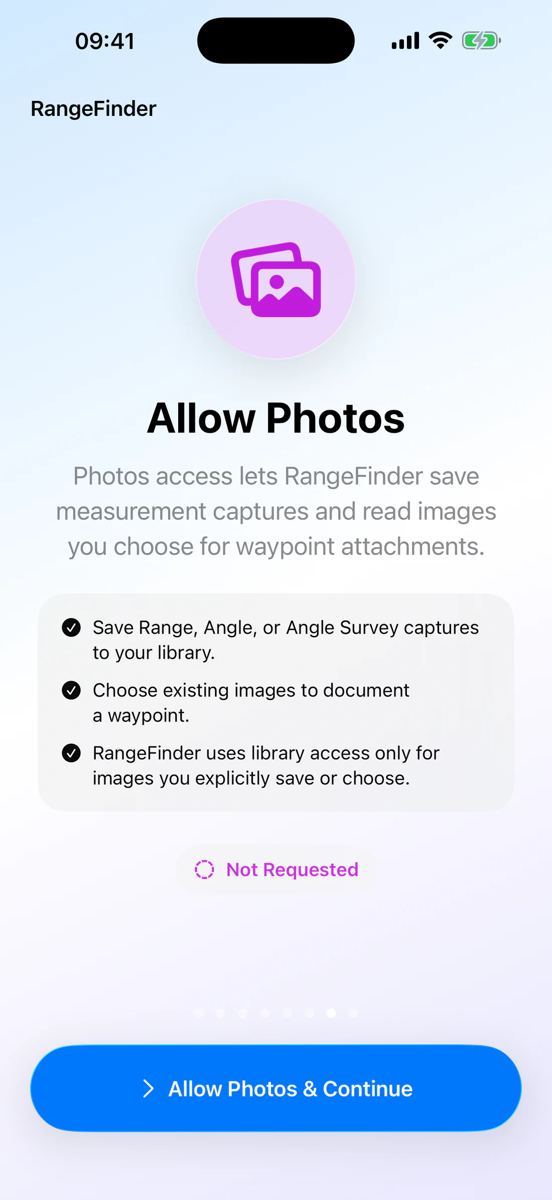
Photos lets you save instrument captures and choose an existing image when
creating a waypoint from EXIF metadata.
Microphone is requested when you choose to add a voice recording to a
waypoint, not during basic measurement.
If you decline a permission, you can continue using unrelated features. To
change the decision later, open iOS Settings → Apps → RangeFinder.
RangeFinder Welcome page with a single Next button.
Onboarding page explaining why RangeFinder needs camera access.
Onboarding page explaining image selection and saving.
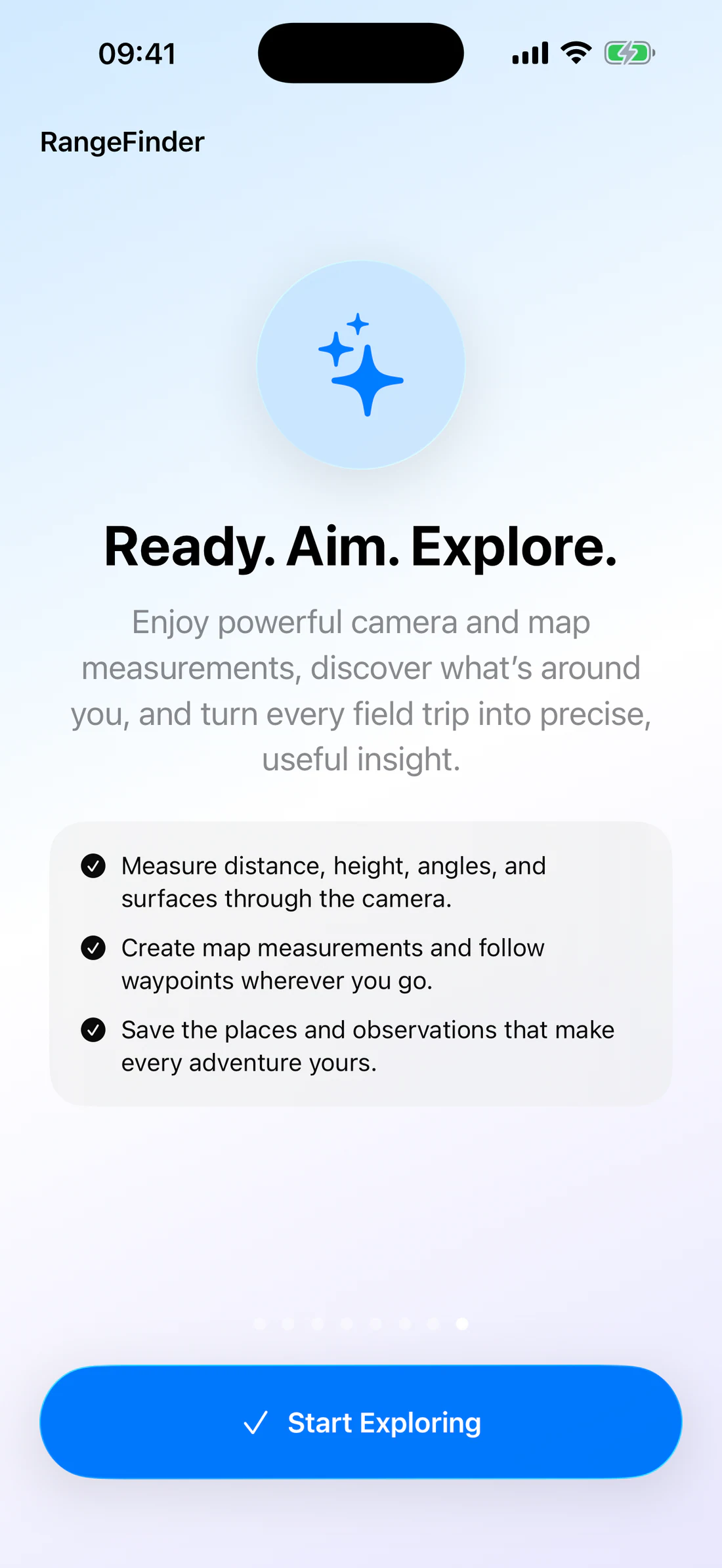
Final RangeFinder onboarding page inviting the user to begin measuring.
2. Choose the measurement method
Situation
Use
Required input or hardware
Result
Target height is known
Known Size → Known Height
Trusted height and visible top/bottom
Estimated distance
Target distance is known
Known Size → Known Distance
Trusted distance and visible top/bottom
Estimated height
Supported LiDAR device; solid target
LiDAR
LiDAR depth camera
Direct slant range
Supported LiDAR device; tracked wall/surface
Surface
AR tracking and detected geometry
Surface raycast range
Saved geographic target
Waypoints
Location, heading, selected visible waypoint
Geodesic distance and camera label
Two map positions
Map → Measurement
Two or more coordinates
Map distance/shape result
Angular orientation or direction change
Angle
Motion/heading sensor
Heading, inclination, roll, A–B
Target subtends a known angular scale
Angle Survey
Calibrated camera/reticle and valid field method
Manual estimate
Selection rules
Prefer LiDAR for a nearby, solid, single-surface target when compatible
hardware is available.
Prefer Known Height only when the height is more trustworthy than the
distance.
Prefer Known Distance only when the distance is more trustworthy than the
height.
Use a map measurement for geographic points; it is not a camera line-of-sight
measurement.
Use Waypoints for navigation context; its distance is based on coordinates,
not camera depth.
Do not substitute one method silently when another is unavailable. The app
preserves this distinction in its method status and saved provenance.
3. Read the Range screen
The Range screen places the live camera behind:
the selected vector reticle;
two draggable shutters in Known Size;
a method and quality capsule;
the result panel;
the mode selector and measurement controls;
Photo and Settings buttons at the top right;
a sensor rail showing available coordinate, altitude, heading, horizon,
inclination, and timestamp information.
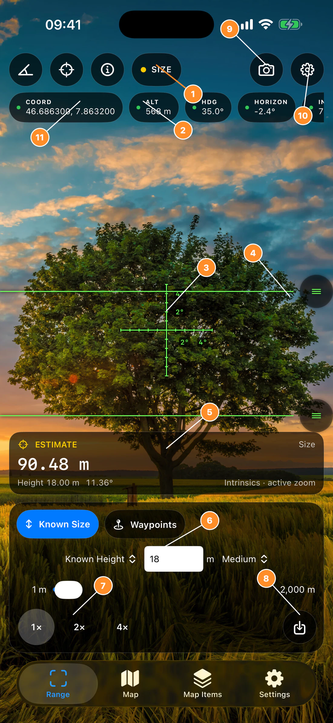
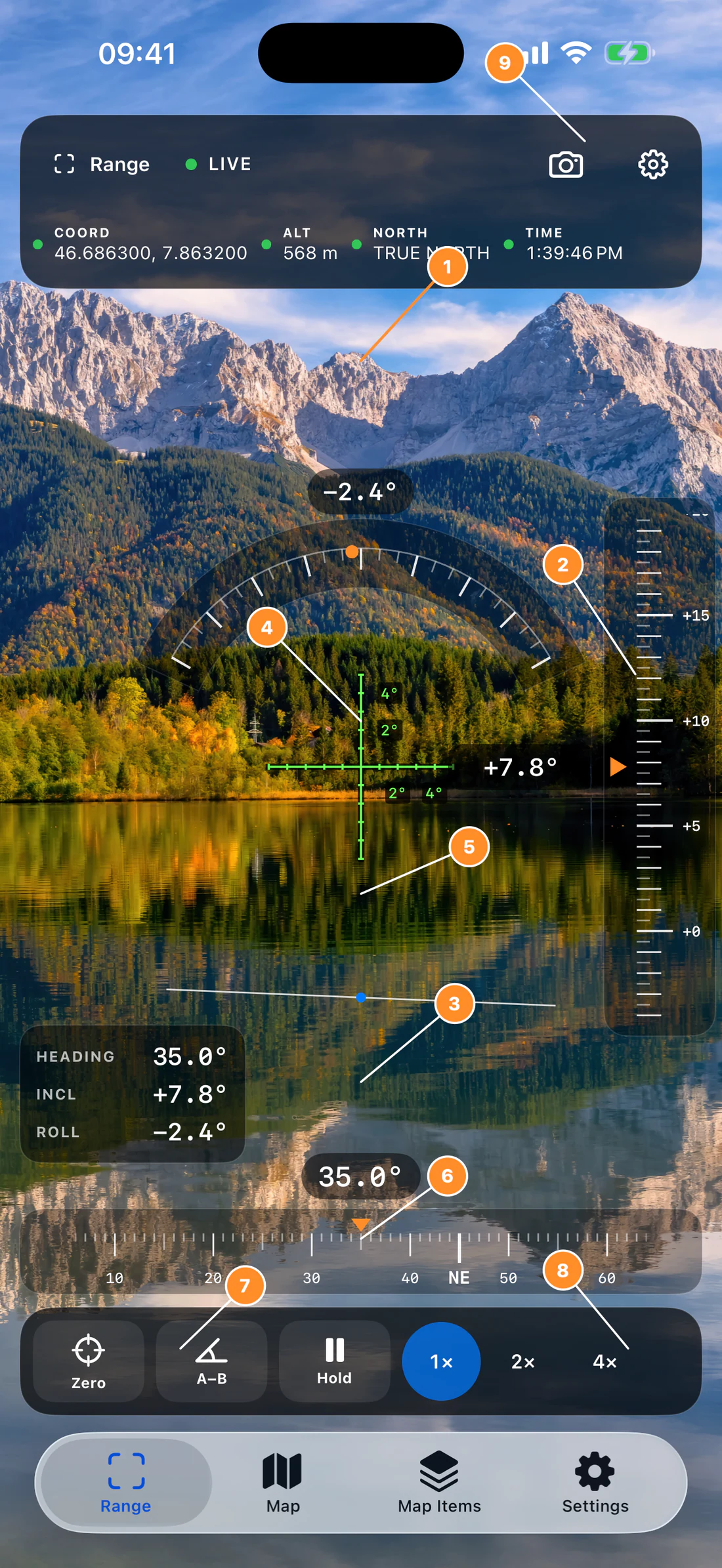
Annotated Range screen identifying its camera measurement controls.
The sensor rail describes context; it does not make an invalid range valid. A
remembered last good coordinate may be shown when the current location is poor.
The warning indicator tells you it is retained data. Do not present it as a
fresh fix.
4. First Known Height measurement
This example estimates the distance to a building whose visible height is known
to be 18 m.
Open Range.
Choose Known Size.
Open the input-mode menu and choose Known Height.
Choose the Medium band and metric units.
Enter 18 in the value field.
Hold the device steady and keep the camera face as square to the building as
practical.
Drag the upper shutter to the top of the 18 m section.
Drag the lower shutter to its bottom.
Confirm that the result panel shows ESTIMATE, a numeric distance, the
known height, and an angular size.
Repeat the alignment. Large variation between repetitions indicates weak
geometry, uncertain endpoints, or an incorrect known height.
Save Observation stores the validated measurement, method, time, sensor
snapshot, provenance, name, note, and any attached capture in RangeFinder’s
measurement history.
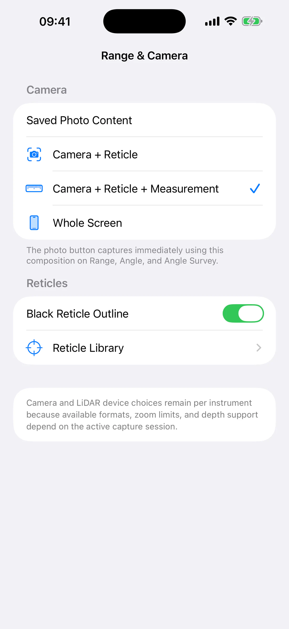
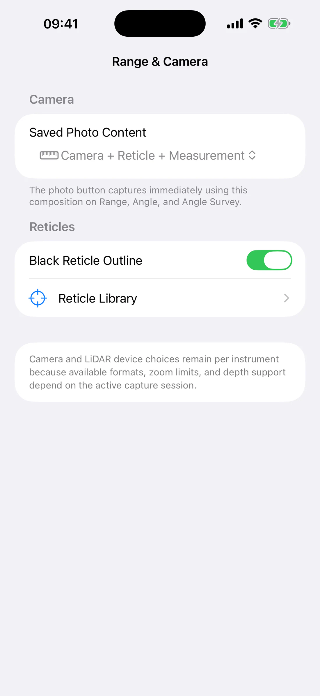
Photo creates an image using the composition selected in Range Settings:
Camera + Reticle, Camera + Reticle + Measurement, or Whole Screen.
The review screen can then save it to Photos or share it.
A photo is not automatically a saved observation, and an observation does not
automatically enter the Photos library.
6. Field checklist
Before accepting a result:
use a clean lens;
confirm the correct camera and zoom;
verify the known height/distance and its units;
keep both shutters on the same physical target;
avoid glass, mirrors, water, thin edges, or mixed surfaces for LiDAR;
wait for the status to become numeric and usable;
hold the device still;
repeat the measurement;
save the observation with a meaningful name and note;
independently verify any important result.
7. If no result appears
Read the guidance line under the result.
Confirm that the selected method is available on the device.
For Known Size, confirm that the input is positive and the lower shutter is
below the upper shutter.
For LiDAR, place the complete target on one matte, solid surface.
For Surface, move the device slowly until AR tracking detects geometry.
Check Camera and Location access in iOS Settings.
Let the device cool if thermal pressure interrupted the camera.
Leave and reopen the instrument if the camera session was interrupted.
RangeFinder does not replace missing or low-quality data with a fabricated
numeric value.
Range and Known Size
The Range workspace combines several measurement methods behind one camera
interface. This chapter explains the common screen and the Known Size method,
which is available without LiDAR.
Range screen anatomy
Annotated Range screen identifying its camera measurement controls.
Mode selector — Known Size, Waypoints, and, on compatible
devices, LiDAR and Surface.
Method status — the selected method and its current quality color.
Reticle — the selected vector reticle from the shared library.
Known Size shutters — draggable horizontal lines defining the visible
angular height.
Result panel — primary result, known or calculated secondary value,
angular size, quality, and guidance.
Known Size controls — Known Height/Distance, numeric input, unit, band,
and slider.
Zoom controls — 1×, 2×, and 4× where supported by the active standard
camera. LiDAR uses its selected depth camera at fixed measurement zoom.
Save Observation — stores the current validated measurement.
Photo — immediately captures using the composition selected in Settings.
Range Settings — display, compass/horizon calibration, sensors, LiDAR,
cameras, ranging, reticle, lens filter, and photo options.
Sensor rail — coordinate, altitude, heading, horizon, inclination, and
timestamp state when available.
On a device without LiDAR, only Known Size and Waypoints appear in the
Range method selector. Surface is hidden with LiDAR because it requires the
supported AR/depth workflow.
How Known Size works
Known Size measures the angular separation between the upper and lower shutters
using the active camera’s delivered intrinsics and zoom configuration.
For a known physical height (H) and measured angular height (\theta), the
distance is:
[
D = \frac{H}{2\tan(\theta/2)}
]
For a known distance (D), the calculated height is:
[
H = 2D\tan(\theta/2)
]
The app performs this calculation from the two shutter rays. You do not need to
calculate the angle yourself. The formulas explain why endpoint placement,
camera configuration, and the trusted input value matter.
Known Size is an estimate, not direct depth. The result panel identifies it
as ESTIMATE and includes the measured angular size.
Estimate distance with Known Height
Result
Calculate the distance to an object when its visible physical height is known.
Before you start
You need:
a target with a trustworthy vertical height;
a clear view of both endpoints of that height;
Camera permission;
the correct unit system and range band;
a steady position with the device not strongly rolled or tilted relative to
the target.
Use the height of the exact section bounded by the shutters. Do not enter the
full building height if a roof, basement, slope, or hidden section is outside
the shutter endpoints.
Steps
Open Range.
Choose Known Size.
Tap the input-mode menu and choose Known Height.
Select Small, Medium, or Large for convenient slider units.
Enter the target height in the numeric field or move the value slider.
Aim at the target and choose a supported standard-camera zoom.
Drag the upper shutter until it touches the top endpoint.
Drag the lower shutter until it touches the bottom endpoint.
Read the primary distance in the result panel.
Confirm that the secondary line shows the height you entered and that an
angular value is present.
Repeat the alignment at least twice.
If the result is important, tap Save Observation, enter a name and
note, and tap Save.
Worked example: 18 m building section
Assume:
trusted height: 18.0 m;
angular height measured from the shutters: approximately 11.36°.
The corresponding calculation is approximately:
[
D = \frac{18}{2\tan(11.36^\circ/2)} \approx 90.5\ \text{m}
]
The exact app result may differ because it uses the delivered camera intrinsics
and the actual shutter rays rather than a rounded example angle.
Verify
A usable Known Height result shows:
ESTIMATE rather than Acquiring or Unavailable;
a numeric primary distance;
the entered height as the secondary value;
an angular size;
guidance referring to camera intrinsics and active zoom.
Move one shutter slightly, realign it, and confirm that the result changes
smoothly. A large jump from a tiny movement means the target occupies too
little of the frame or the endpoint is ambiguous.
Accuracy and limitations
The largest error sources are:
incorrect or approximate known height;
placing a shutter on the wrong physical endpoint;
perspective when the top and bottom are not in a plane suited to the model;
camera roll, severe inclination, motion, or unstable framing;
target occupying too few pixels;
changing camera/zoom while aligning;
an unverified camera configuration;
measuring a partially hidden target.
Move closer or use a supported optical/active-camera zoom when the target is
too small, but realign both shutters after any camera or zoom change.
Estimate height with Known Distance
Result
Calculate the physical height of a visible object when the camera-to-target
distance is known.
Before you start
You need a trustworthy distance that corresponds to the geometry being
measured. A map distance to the building footprint may not equal the camera
line-of-sight distance. For important work, measure the reference distance with
an appropriate independent tool.
Steps
Open Range and choose Known Size.
Choose Known Distance from the input-mode menu.
Select a band whose units suit the reference distance.
Enter the distance.
Keep the device at the position from which that distance was established.
Drag the upper and lower shutters to the object’s visible endpoints.
Read the calculated height as the primary result.
Confirm that the secondary line shows the distance you entered.
Repeat the shutter placement and compare results.
Save the observation with the source of the reference distance in its note.
Worked example: target 50 m away
Assume:
trusted distance: 50.0 m;
measured angular height: approximately 3.44°.
Then:
[
H = 2(50)\tan(3.44^\circ/2) \approx 3.0\ \text{m}
]
The exact app value uses the current shutter rays and camera configuration.
Verify
A usable Known Distance result shows:
ESTIMATE;
a numeric primary height;
the entered distance as the secondary value;
the measured angular size.
If you move forward or backward after establishing the known distance, the
input is no longer valid. Update the distance or return to the reference point.
Accuracy and limitations
Known Distance inherits uncertainty from both the reference distance and
shutter placement. The calculated height can be misleading when:
the reference distance is horizontal map distance but the target requires
slant distance;
the camera moved after the distance was measured;
the target top and bottom are not the intended endpoints;
only part of the target is visible;
the target is very small in the image.
Choose Small, Medium, or Large
The band changes the input unit, slider range, and slider step. It does not
change the measurement formula or impose a hard limit on manually entered
values.
Band
Metric
Imperial
Typical use
Small
1–500 cm, step 1 cm
1–200 in, step 1 in
people, doors, signs, small structures
Medium
1–2,000 m, step 1 m
1–6,500 ft, step 1 ft
buildings, fields, nearby terrain
Large
1–100 km, step 0.1 km
1–60 mi, step 0.1 mi
distant landmarks and long references
Values outside the slider range
The text field accepts a positive manual value outside the selected band’s
slider range. The app preserves the value and displays Manual value preserved
outside the … slider range. The slider remains clamped to its convenient
range; it does not overwrite the manual value until you move it.
While editing, the field may be temporarily empty. The last valid numeric value
is retained until you enter a new positive value. Use the current locale’s
decimal separator.
Place and reset the shutters
The upper and lower shutters are independent horizontal controls. Their
positions persist between sessions.
Drag anywhere on the 44-point handle to improve touch sensitivity.
Keep the upper shutter above the lower shutter.
Align to repeatable edges, not shadows or soft foliage.
After rotating the device or changing zoom, verify both endpoints again.
To restore the initial symmetric positions, open Range Settings → Ranging
and tap Reset Known Size Sliders.
The default positions are symmetrical around the center of the measurement
area.
Use zoom correctly
Known Size and Waypoints can use standard-camera zoom where supported.
Establish your framing.
Choose 1×, 2×, or 4×.
Wait for the camera configuration to settle.
Realign both shutters.
Record the result only after the panel returns to a usable state.
Do not compare a 1× shutter position directly with a 2× position; zoom changes
the visible field of view. The app includes the active zoom in its calculation.
LiDAR does not show these manual zoom buttons because the selected depth camera
uses its fixed measurement zoom.
Understand result quality
State
Meaning
Action
Acquiring
Valid camera geometry or sensor data is not ready
Hold steady and follow the guidance
Estimate
Known Size produced a calculated result
Verify input, endpoints, zoom, and repeatability
Stable
Direct/surface sampling reached a usable state
Keep the target on one surface and record if needed
Medium quality
A result exists with reduced confidence
Repeat and use caution
Low quality
Geometry, motion, target, or calibration is weak
Change conditions; do not rely on the value
Unavailable
Permission, camera, sensor, session, or hardware is unavailable
Correct the stated requirement
Status color is supporting information, not a guarantee of field accuracy.
Always interpret the status, number, guidance, and physical setup together.
Save an observation
Save Observation becomes available for a validated Known Size, LiDAR, or
Surface result.
Tap the Save Observation icon in the lower control panel.
Enter a concise Name.
Add Notes describing the target, known-value source, camera position,
environmental conditions, or independent reference.
Review Method, Distance, and whether a Capture is attached.
Tap Save.
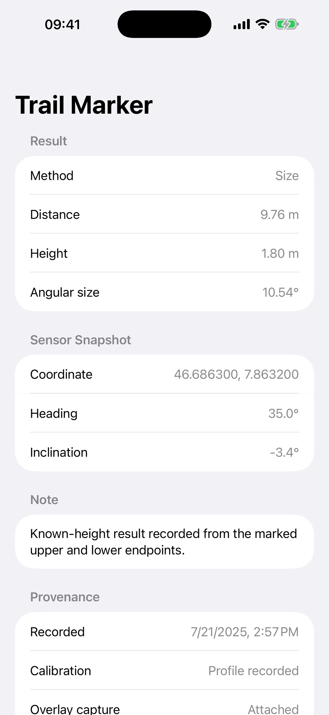
The implemented Measurement History detail view can include distance, height,
angular size, sensor snapshot, note, recorded time, calibration provenance, and
overlay-capture state.
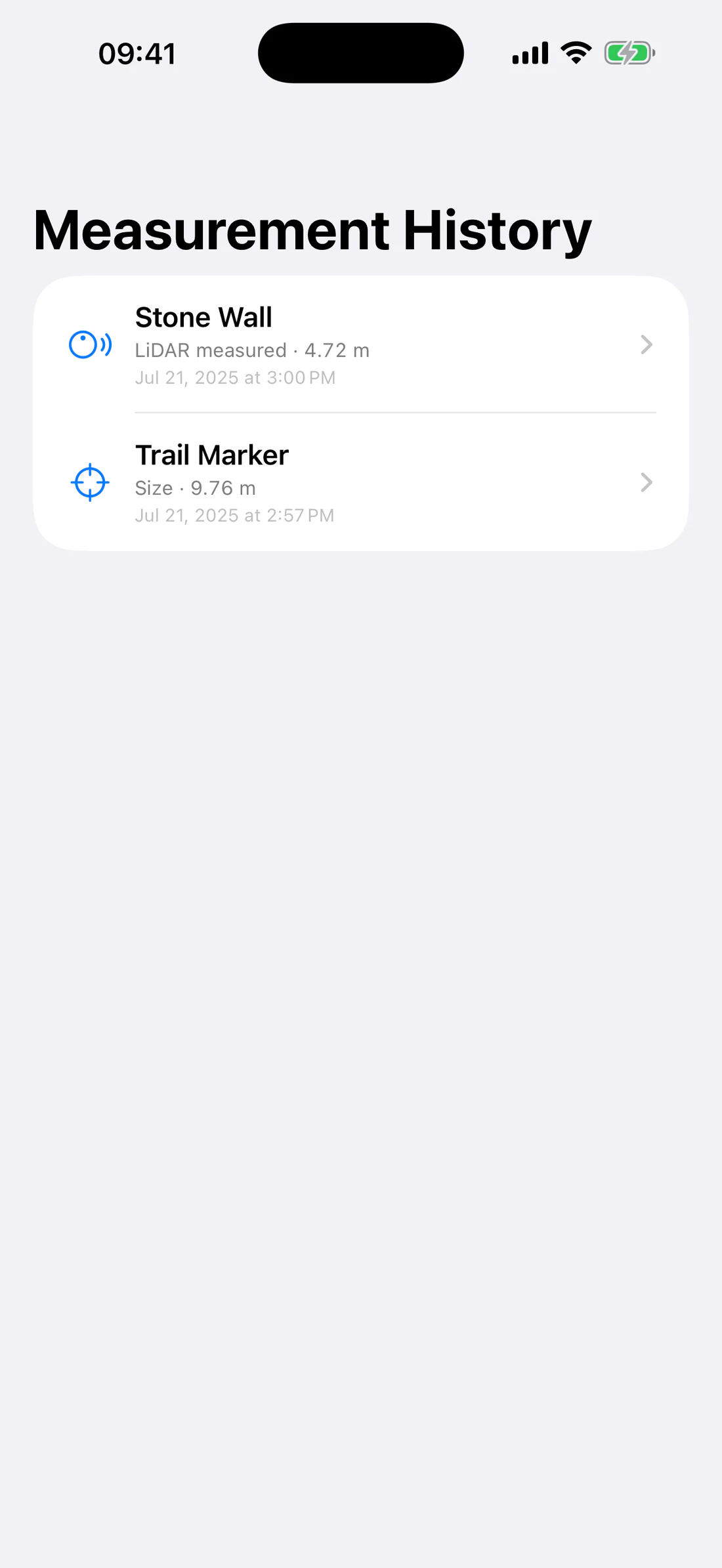
Measurement History with saved Known Size and LiDAR observations.
Saved Range observation showing result, sensor snapshot, note, and provenance.
Deleting an observation does not delete an original image that you separately
saved to Photos.
Related Range settings
Open the gear button at the top right of Range.
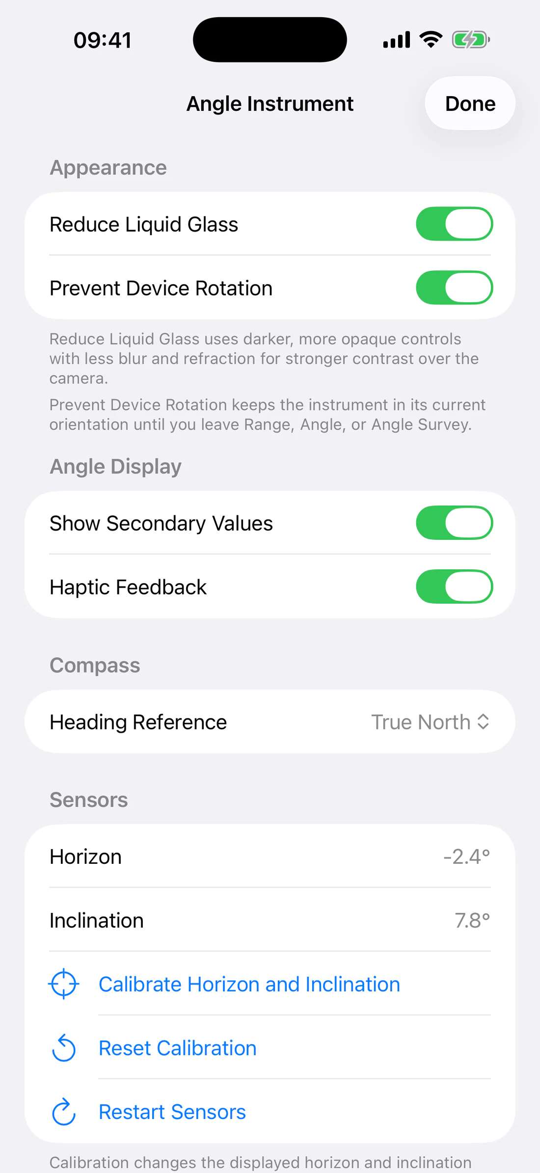
Appearance — Reduce Liquid Glass and Prevent Device Rotation.
Compass — horizon/inclination calibration shared with instrument context.
Sensors — horizontal and vertical reticle zero; Reset Zero.
LiDAR — depth camera, reference distance, calibration and reset, when
available.
Cameras — standard rear-camera selection and supported zoom range.
Ranging — Method, Units, Range Band, Reset Known Size Sliders.
Reticle — reticle library, calibration status, angular spacing, labels,
black contrast outline, line width, opacity, and color.
Lens Filter — clear or color overlay.
Photo — the composition used immediately when Photo is pressed.
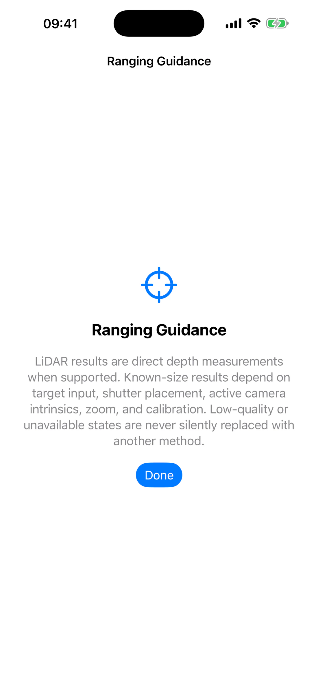
Ranging Guidance explaining the difference between LiDAR and Known Size results.
The Ranging Guidance sheet explains that LiDAR is a direct depth result
while Known Size depends on target input, shutter placement, active camera
intrinsics, zoom, and calibration. An unavailable method is not silently
replaced with another measurement.
Troubleshooting Known Size
The primary value is a dash
Confirm Camera permission.
Confirm the input is a positive number.
Make sure the lower shutter is below the upper shutter.
Wait for the camera configuration.
Increase the target’s size in the frame.
Return to a supported camera zoom.
The result changes too much
Use a tripod or brace the device.
Choose harder, repeatable endpoints.
Increase the target’s image size.
Confirm that the known value covers exactly the measured section.
Repeat without moving the camera.
The input looks wrong after changing bands
The underlying input is stored in meters and converted to the selected band.
Check the unit symbol. A manual value outside the new slider range remains
valid and is not discarded.
The shutters moved after changing orientation
Confirm whether Prevent Device Rotation is enabled. Even when the interface
is locked, physical camera geometry changes as the device moves; recheck the
endpoints before saving.
LiDAR and Surface
LiDAR and Surface appear in Range only on compatible devices. They use related
hardware but produce different results:
LiDAR samples direct depth inside the central target.
Surface raycasts from the center of the camera through AR world tracking
to detected geometry.
Neither mode is a substitute for a certified laser rangefinder or a
life-safety instrument.
Device availability
On a non-LiDAR device, Range shows Known Size and Waypoints. LiDAR and
Surface are hidden rather than disabled. On compatible hardware, the selector
adds LiDAR and Surface after those two modes.
LiDAR and Surface require a physical device. Simulator can show layout fixtures
but cannot provide valid depth or AR measurement evidence.
Measure direct range with LiDAR
Result
Obtain the slant range from the active depth camera to one continuous target
surface.
Before you start
Clean the camera/depth-sensor area.
Choose an opaque, matte, solid target large enough to fill the sampling
region.
Keep the device within a practical range for its depth hardware.
Let an overheated device cool before measuring.
Steps
Open Range.
Choose LiDAR.
Place the central target entirely on one surface.
Keep wall/floor boundaries and foreground objects outside the target.
Hold still while the status is Acquiring.
Read the distance only after a numeric Stable or usable
Medium Quality result appears.
Repeat from the same position.
Tap Save Observation to retain the method, result, sensor snapshot, and
provenance.
Example: 3.000 m reference board
Place a flat board at an independently measured 3.000 m reference distance.
Keep the board perpendicular enough to provide one broad surface.
Aim at its center and obtain several stable readings.
Repeat at approximately 1 m, 3 m, and a practical longer distance.
Record the observed spread and conditions.
Use the measured 3.000 m value as a calibration reference only when the setup
itself is trustworthy.
Result details
The primary value is slant range. When available, the secondary MAD value is
the median absolute deviation of recent accepted samples. A smaller spread
usually indicates a more consistent sample window, but it does not prove the
target distance is correct.
Understand LiDAR quality
State
Meaning
Response
Acquiring
Not enough accepted depth samples
Hold still and keep the target on one surface
Stable
Recent samples are sufficiently consistent
Repeat, then save if needed
Medium Quality
A usable result has more spread
Improve aim and repeat
Low Coverage
Too little of the sample region has valid depth
Use a larger/closer surface
Mixed Surfaces
Samples contain separated depth groups
Move away from edges or obstructions
Unstable
Recent ranges vary too much
Brace the device and use a static target
Excessive Motion
Device movement invalidates sampling
Stop moving and wait
Unavailable
Hardware, permission, depth, session, or thermal state is unavailable
Follow the displayed recovery guidance
Reflective or transparent targets can return missing, unstable, or misleading
depth. The correct response is to change the target or use a different
measurement method—not to record the first number.
LiDAR camera and fixed zoom
Open Range Settings → LiDAR to see the selected depth camera. LiDAR uses
that camera at fixed measurement zoom, so the 1×, 2×, and 4× standard-camera
buttons are hidden in LiDAR mode.
Standard rear-camera selection is separate under Cameras and applies to
Known Size, Waypoints, Angle, and Angle Survey as appropriate.
Calibrate a LiDAR result
Calibration compensates a repeatable device/configuration offset; it cannot fix
mixed surfaces, bad reference geometry, motion, or unsuitable material.
Establish a reference distance with an independent tool.
Aim LiDAR at one stable surface at that distance.
Wait for a stable result.
Open Range Settings → LiDAR.
Enter the reference distance in meters.
Tap Calibrate Current Result.
Confirm that calibration was saved for the active camera, format, and zoom.
Recheck at several distances.
Use Reset Active Calibration to discard the profile for the active
configuration. A stable current LiDAR result is required to calibrate.
Measure a detected surface
Result
Obtain the distance along the center camera ray to geometry detected by AR
world tracking.
How Surface differs from LiDAR
LiDAR direct mode summarizes depth samples in its target. Surface uses an AR
raycast against detected geometry. A wall can therefore be measurable after AR
has built enough geometry even though the result is not the same sampling
pipeline as direct LiDAR.
Steps
Open Range and choose Surface.
Move the device slowly so AR can detect the room or outdoor surface.
Point the central target at the desired location.
Wait while the guidance says to move slowly or detect surfaces.
When a numeric result appears, hold on the same detected surface.
Repeat without targeting an edge.
Save the observation if required.
Wall example
Aim first near the center of a broad wall. Then aim at the wall/floor boundary.
The boundary is less reliable because a small pointing change can move the
raycast between two different surfaces.
The device did not report compatible LiDAR hardware. Use Known Size,
Waypoints, Angle, Angle Survey, or map measurement instead.
LiDAR never becomes stable
fill the target with one matte surface;
move closer within practical sensor range;
stop device/subject movement;
remove foreground edges;
clean the sensor area;
let the device cool;
leave and reopen Range after an interruption.
Surface keeps asking you to move
Move slowly across visible texture and corners so AR can establish tracking.
Return the target to the desired point only after geometry is detected.
Camera is black or interrupted
Check Camera permission, bring the app to the foreground, close another app
using the camera, allow the device to cool, and reopen the instrument. The app
must show Unavailable rather than inventing a range while the capture session
is interrupted.
Angle and A–B measurement
Angle is a camera instrument for live heading, inclination, and roll. It also
records two directions, A and B, and calculates their spatial separation.
Open Angle
From Range, use the dedicated Angle switch button. The Angle screen includes:
The horizon line rotates opposite device roll so that it continues to represent
the physical horizon while the phone rotates.
Read heading, inclination, and roll
Heading is the direction around the horizon, expressed in degrees from
the active north reference.
Inclination is the camera’s up/down angle.
Roll is rotation around the viewing axis.
Keep the device away from magnets, speakers, steel structures, magnetic cases,
and strong electrical fields. Compare the heading with a known direction when
accuracy matters.
Set a relative Zero
Zero captures the current fresh direction as a relative reference.
Aim at the reference direction.
Wait for valid heading and motion.
Tap Zero.
Rotate or tilt to read the change relative to that reference.
Tap Zero again to clear the relative reference.
The status indicates ZERO ACTIVE while the reference is applied. Zero does
not recalibrate the device compass; it changes the instrument’s reporting
reference.
Hold a reading
Wait for fresh valid heading and motion data.
Tap Hold.
Inspect or photograph the frozen values.
Tap Release to resume live updates.
Hold freezes the displayed reading; it does not stop the camera or permanently
save an observation.
Measure the angle from A to B
Result
Record two viewing directions from one position and calculate their spatial
angular separation and component changes.
Before you start
Use a physical device with fresh heading and motion data.
Choose two repeatable visual points.
Stand in one place and rotate the device without translating it.
Keep magnetic interference low.
Steps
Open Angle.
Start the A/B workflow.
Aim the reticle at the first point.
Hold steady and capture A.
Rotate/tilt toward the second point without changing your standing position.
Use the persistent A marker to understand the stored first direction. If A
leaves the camera view, its marker remains on the appropriate screen edge.
Aim precisely at the second point and capture B.
Read the spatial A–B angle.
Compare the heading, inclination, and roll components when shown.
Reset the workflow before starting another pair.
Example: roof corners
Stand at one marked position. Capture A at the left roof corner and B at the
right roof corner. The spatial A–B value describes the angle between those
viewing directions.
Do not walk sideways between A and B. Translating the device changes the
geometry and means the two rays no longer originate from the same point.
Interpret A–B values
Do not confuse:
heading change, a horizontal/azimuth component;
inclination change, a vertical component;
roll, device rotation around the view axis;
spatial A–B angle, the three-dimensional angular separation between the
stored direction vectors.
The spatial value is not necessarily the arithmetic sum of the component
changes.
Angle Settings
Angle uses the common instrument settings pattern:
Appearance — Reduce Liquid Glass and Prevent Device Rotation.
Compass — horizon/inclination calibration.
Sensors — reference/zero controls where exposed.
Cameras — standard camera selection.
Reticle — shared library, spacing, labels, outline, line width, opacity,
and color.
Lens Filter.
Photo — saved photo composition.
Angle Settings with Display, Compass, Sensors, Cameras, Reticle, and Photo Button sections.
Prevent Device Rotation keeps the interface in its current orientation until
you leave Range, Angle, or Angle Survey. The live horizon and sensor angles
still respond to physical motion.
Accuracy and recovery
Wait for a fresh reading before Zero, Hold, A, or B.
Repeat A and B in both directions to assess consistency.
Recalibrate the system compass if iOS indicates poor heading accuracy.
Use horizon calibration only from a known level reference.
Keep the phone in one physical position for A–B.
Treat remembered or stale sensor context as a warning.
If orientation changes, confirm the interface and horizon remain aligned
before recording.
Reticles and Angle Survey
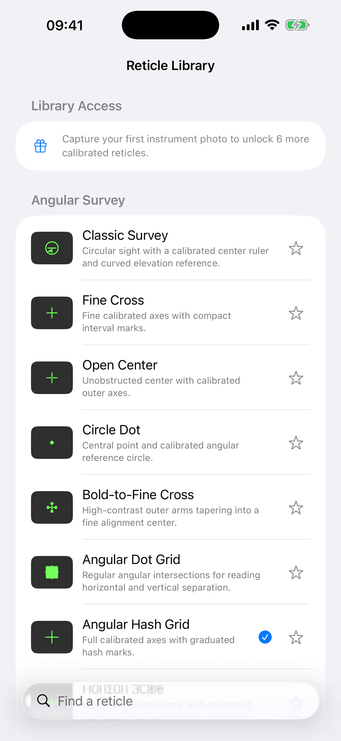
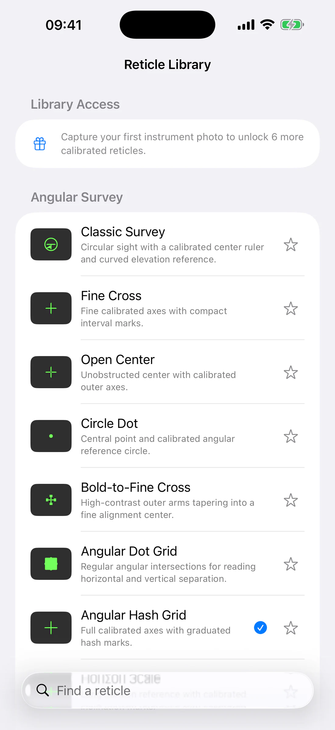
Range, Angle, and Angle Survey use one shared vector reticle library. Vector
marks remain sharp at different screen and photo resolutions. Calibrated marks
use active camera intrinsics/configuration; an approximate preview is for
layout selection only.
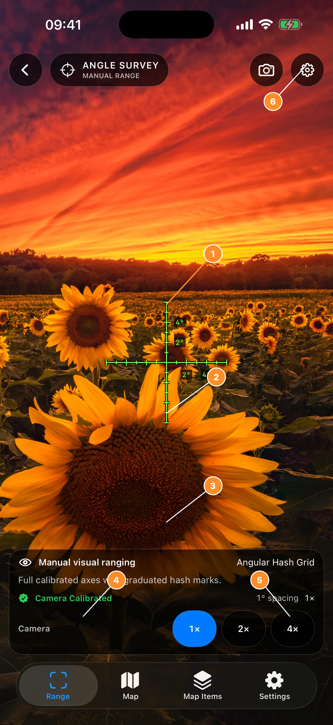
Angle Survey is a manual optical instrument. It does not silently infer a
distance from camera or motion sensors.
Open Angle Survey
From Range, tap the dedicated Angle Survey switch button. The screen contains:
the selected vector reticle;
live camera and supported zoom;
Photo and Angle Survey Settings at the top right;
camera-calibration status;
a compact measurement panel when the selected reticle supports it.
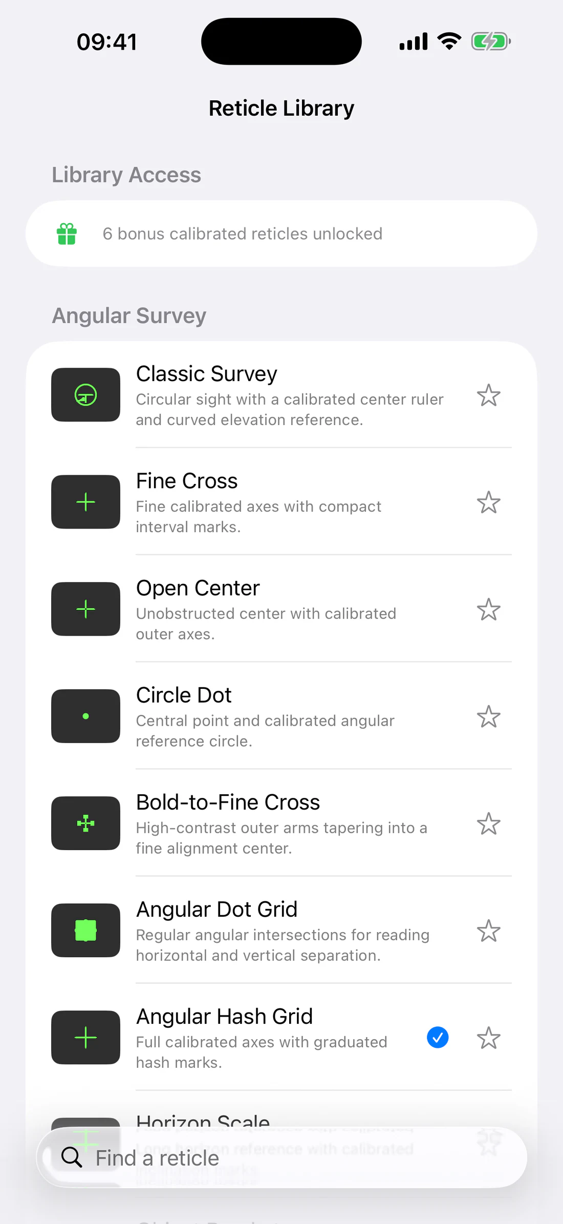
Center a compact subject with a clear reference ring
Bold-to-Fine Cross
Acquire quickly, then refine at the thin center
Angular Dot Grid
Compare horizontal and vertical angular offsets
Angular Hash Grid
Count labeled angular intervals
Horizon Scale
Leveling and horizontal angular comparison
Object Brackets
Compare a subject against symmetric bounds
Polar Grid
Radial angle and direction comparison around center
Reticle Library showing all 10 included styles and no Premium/Photography section.
Capture bonus reticles
After the first successful instrument photo, six additional reticles unlock:
Concentric Circles.
Center Ruler.
Quadrant Scale.
Double Circle Cross.
Split Axis.
Vertical Angle Ladder.
Library Access before first instrument photo; explain six-style bonus.
The bonus is earned after a successful rendered capture, not merely by opening
the camera. Premium/Photography packs remain hidden in this release and are not
part of the published selector.
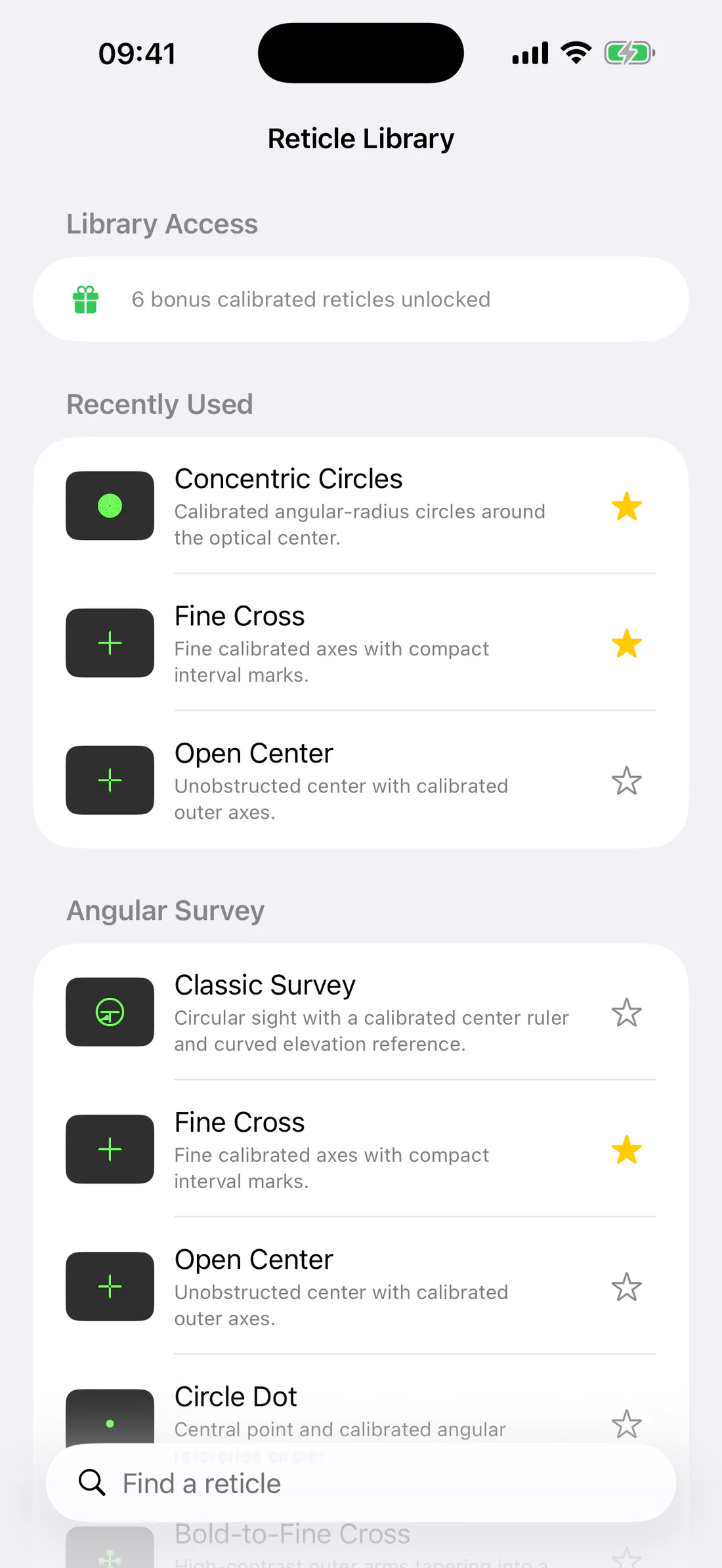
State after first successful capture; bonus styles visible.
Favorites and Recently Used
Use Favorites for reticles needed repeatedly in the field. Recently Used
reduces the need to search the full visible library. Both sections refer to the
same shared reticle definitions, so a selection is consistent across
instruments that support it.
Star two styles, select one, reopen; show Favorites/Recently Used behavior.
Angular spacing
Supported spacing choices are:
15 arcminutes (15′);
30 arcminutes (30′);
1 degree (1°);
2 degrees (2°);
5 degrees (5°).
Spacing defines the intended angular interval between calibrated marks for
reticles that use the common angular grid. Larger spacing must not cause labels
to overwrite dashes; labels sit beside their corresponding marks.
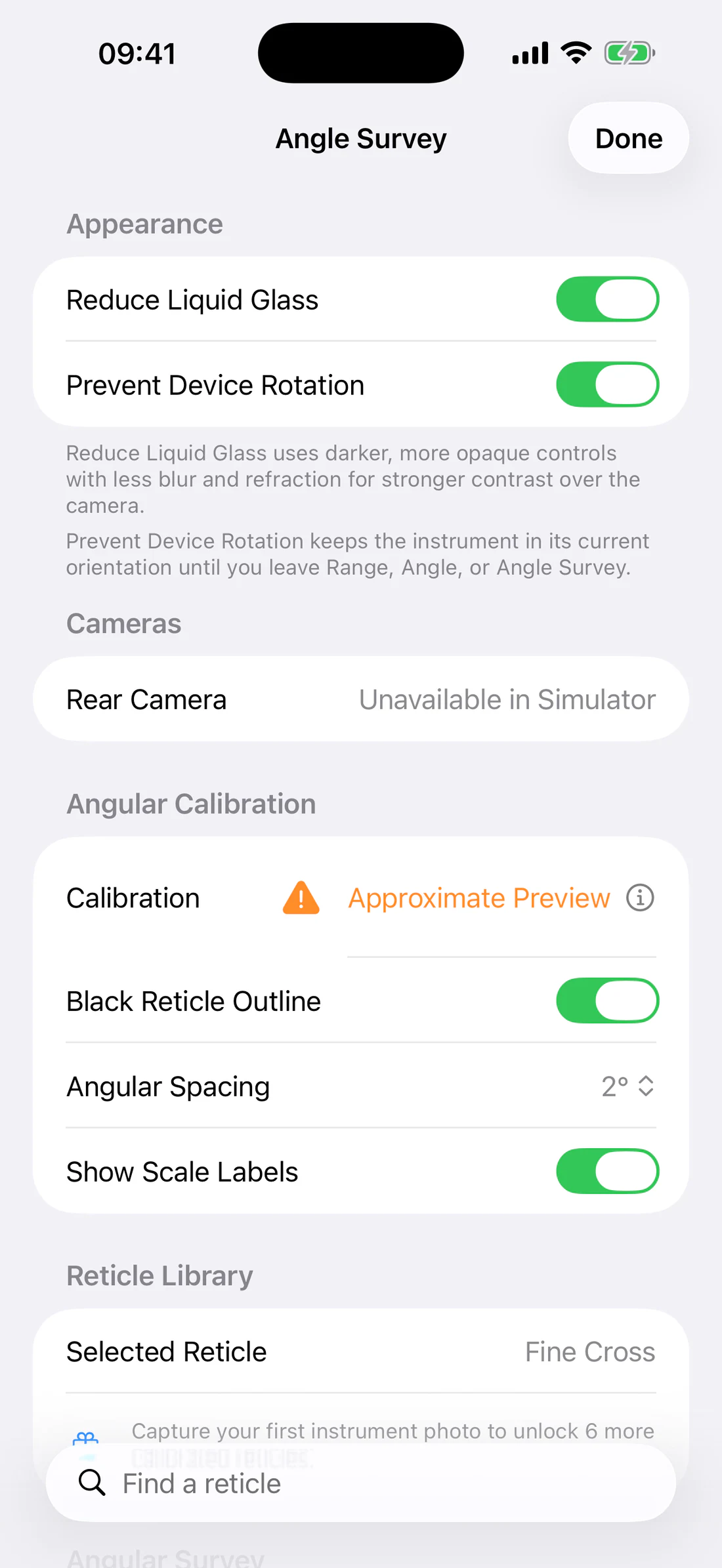
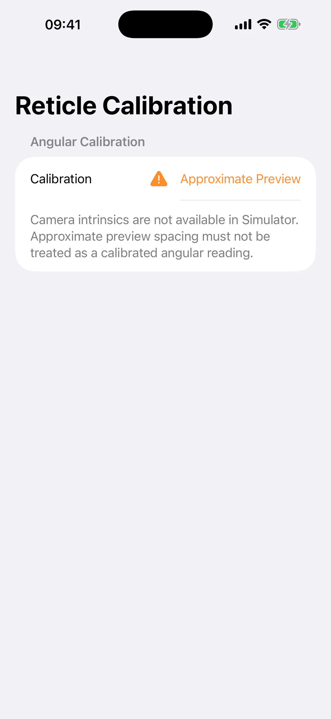
Camera Calibrated and Approximate Preview
Camera Calibrated means the reticle renderer has valid active camera
intrinsics and configuration, including the visible aperture, zoom, and
orientation used to map angular intervals to pixels.
Approximate Preview means the library can show the reticle’s shape but
cannot claim that the marks currently represent their labeled angles. Do not
take measurements from an approximate preview.
Simulator status row showing Approximate Preview and warning copy.
Changing camera, zoom, orientation, or capture configuration can change the
calibrated pixel spacing. Wait for the new configuration and verify the status.
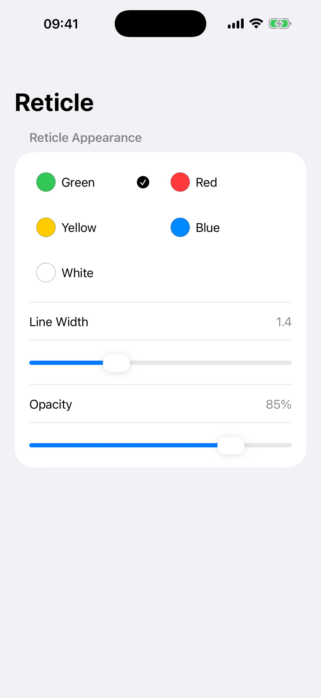
Appearance controls
The shared library provides:
Show Scale Labels;
Black Reticle Outline for contrast on bright or similarly colored
backgrounds;
Line Width;
Opacity;
actual color-selection swatches;
lens filters;
Favorites and Recently Used.
Settings showing actual color circles plus line-width and opacity sliders.
Use a black outline with bright reticle colors over sky, snow, water, or light
walls. Reduce opacity only enough to reveal the target; marks must remain
readable in the saved image.
Example: Angular Hash Grid at 1°
Open Angle Survey Settings.
Select Angular Hash Grid.
Set Angular Spacing to 1°.
Enable Show Scale Labels.
Confirm Camera Calibrated.
Center the first subject on the optical center.
Count full and partial intervals to the second subject.
Record the angular separation and active zoom.
Labels describe angular marks; they are not ballistic or weapon-specific data.
The library is intended for optical surveying, alignment, composition, and
angular comparison.
Manual range from angular size
If a target’s physical size (S) and measured angular size (\theta) are
known, a manual estimate can use:
[
D = \frac{S}{2\tan(\theta/2)}
]
Use consistent units. For small angles, the common approximation
(D \approx S/\theta) requires (\theta) in radians, but the exact relationship
is preferred.
Example: a 2.0 m object spanning 2° is approximately:
[
D = \frac{2.0}{2\tan(1^\circ)} \approx 57.3\ \text{m}
]
Uncertainty in object size and interval reading directly affects the result.
Reticle limitations
Calibration is strongest near the intended visible camera geometry.
Lens distortion and cropping make edge interpretation more sensitive.
Digital screenshots of approximate previews are not calibration evidence.
A reticle cannot determine the real physical size of an unknown target.
Changing zoom requires recalculated spacing.
A thick line can conceal a small endpoint.
A 5° circle/grid must remain a valid geometric circle/scale, not a stretched
decorative shape.
Never infer unsupported precision from a labeled interval.
Photos and observations
RangeFinder separates a saved measurement record from an exported image.
Save Observation stores structured measurement data inside the app.
Photo immediately renders the composition selected in instrument
settings.
Save to Photos copies the reviewed image into the system photo library.
Share exports the rendered image through the system share sheet.
Choose saved photo content
Open the relevant Range, Angle, or Angle Survey settings and select Saved
Photo Content:
Composition
Contents
Camera + Reticle
Camera image, lens filter, and reticle
Camera + Reticle + Measurement
Camera/reticle plus the measurement overlay
Whole Screen
Complete instrument interface as displayed
The setting is shared by the instrument capture workflow. Pressing Photo does
not open a mode menu; it performs the selected composition immediately.
Settings → Range & Camera → Saved Photo Content with all three options.
Capture and save a photo
Prepare a valid instrument state.
Tap Photo once at the top right.
Wait for the Range Capture review.
Inspect reticle scale, measurement overlay, orientation, and crop.
Tap Save to Photos or Share.
After a successful Photos save, dismiss the blue-tinted OK confirmation.
Tap Done to close review.
Reticles and measurements are rendered at photo scale so they retain the same
visual prominence as the instrument rather than becoming two or three times
smaller.
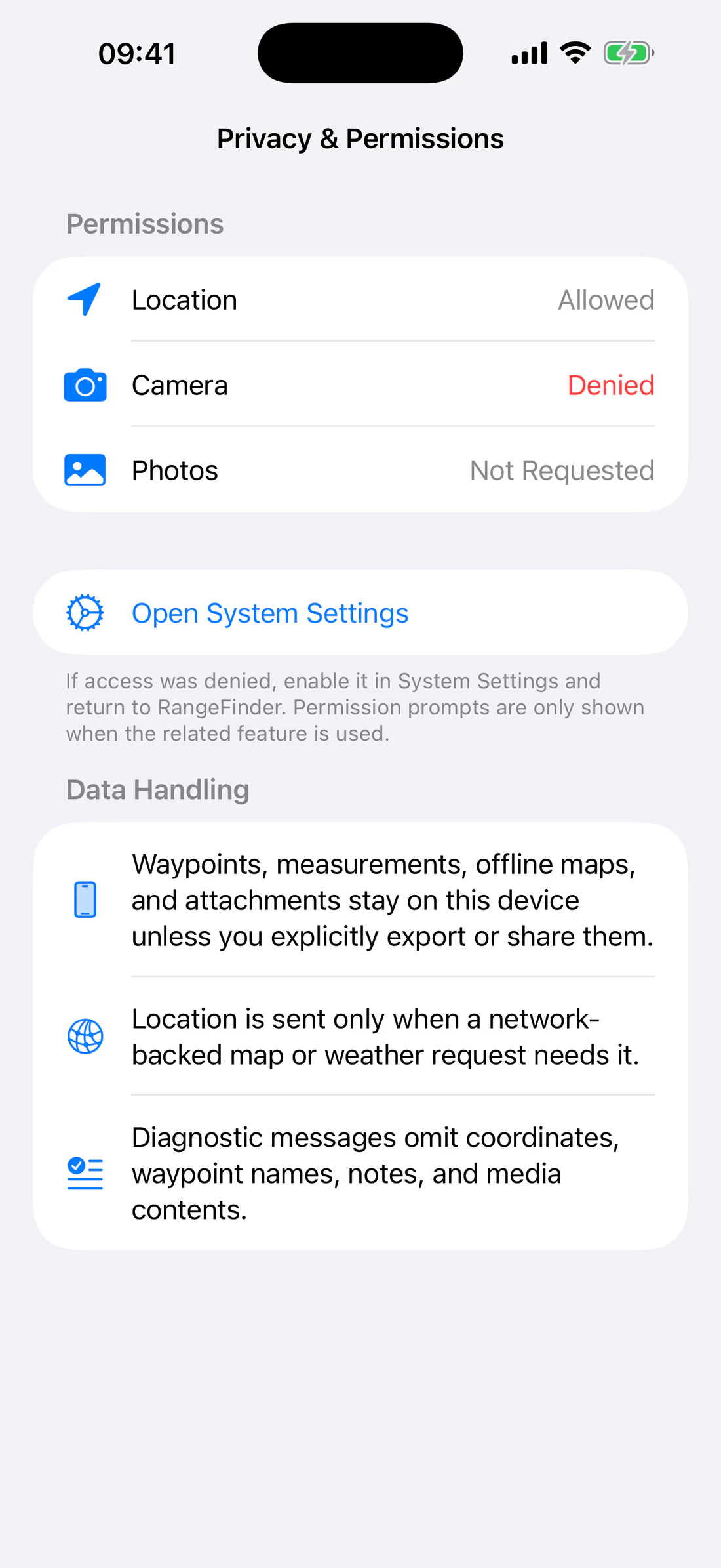
Photos permission
RangeFinder requests photo-library access from the onboarding Photos page or
when the related action requires it. If saving fails because access is denied:
Tap Open Settings in the recovery alert.
Allow the required Photos access for RangeFinder.
Return to the app.
Retry Save to Photos from a newly rendered capture if the previous review
is no longer available.
The app must show a clear error instead of crashing when the photo library is
unavailable.
Save an observation
A validated Known Size, LiDAR, or Surface result can be stored as an
observation.
Tap Save Observation.
Enter a meaningful Name.
Add Notes describing the target, reference source, camera position,
conditions, and independent verification.
Review method, distance, and capture attachment state.
Tap Save.
An observation may contain:
method and result;
Known Size height/distance and angular size;
timestamp;
coordinate, heading, inclination, and other available sensor snapshot;
calibration/profile provenance;
note;
a reference to an instrument capture.
Measurement History with saved Known Size and LiDAR observations.
Saved Range observation showing result, sensor snapshot, note, and provenance.
Observation and Photos independence
Saving an observation does not automatically add an image to Photos. Saving an
image to Photos does not automatically create a structured observation.
Deleting an observation does not delete a separately saved Photos image.
Measurement History navigation requirement
The current code contains Measurement History list and detail screens, but the
shipping navigation must expose a visible entry before this guide publishes a
user path to them. Until that app gap is resolved, screenshots may be captured
with a Debug guide scenario only and the public guide must not claim an
inaccessible path.
Capture troubleshooting
Capture image file is not available
wait for the live camera before pressing Photo;
ensure the app is foreground active;
close another app using the camera;
leave and reopen the instrument after interruption;
allow the device to cool;
use a composition supported by the active instrument.
Whole Screen is blank
Retry only after the camera frame and interface are visible. The complete
screen capture must composite a valid camera frame with the current UI before
the review is presented.
Saved drawing is too small
Verify that the current build renders the reticle and measurement using the
captured photo’s pixel dimensions rather than reusing unscaled screen points.
Camera becomes black
Camera sessions can be interrupted by backgrounding, another camera client,
system pressure, thermal pressure, configuration changes, or unavailable
hardware. RangeFinder should suspend and resume deliberately and show a useful
Unavailable state while recovery is in progress.
Maps, sources, and coordinates
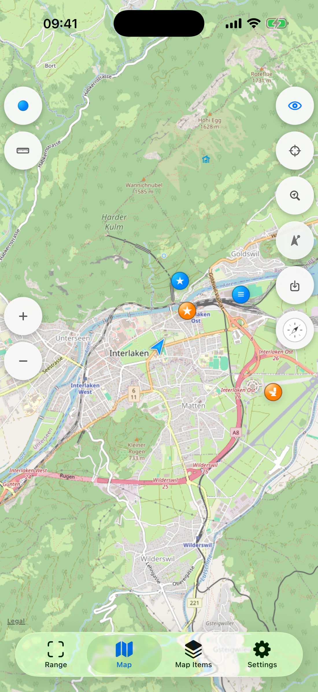
The Map workspace combines navigation, map-source selection, waypoints,
coordinate tools, measurements, offline-area selection, waypoint tracking, and
Map Compass. Raster, vector, and Apple renderers keep the same product
workflows while preserving renderer-specific pan, zoom, and rotation behavior.
Map controls
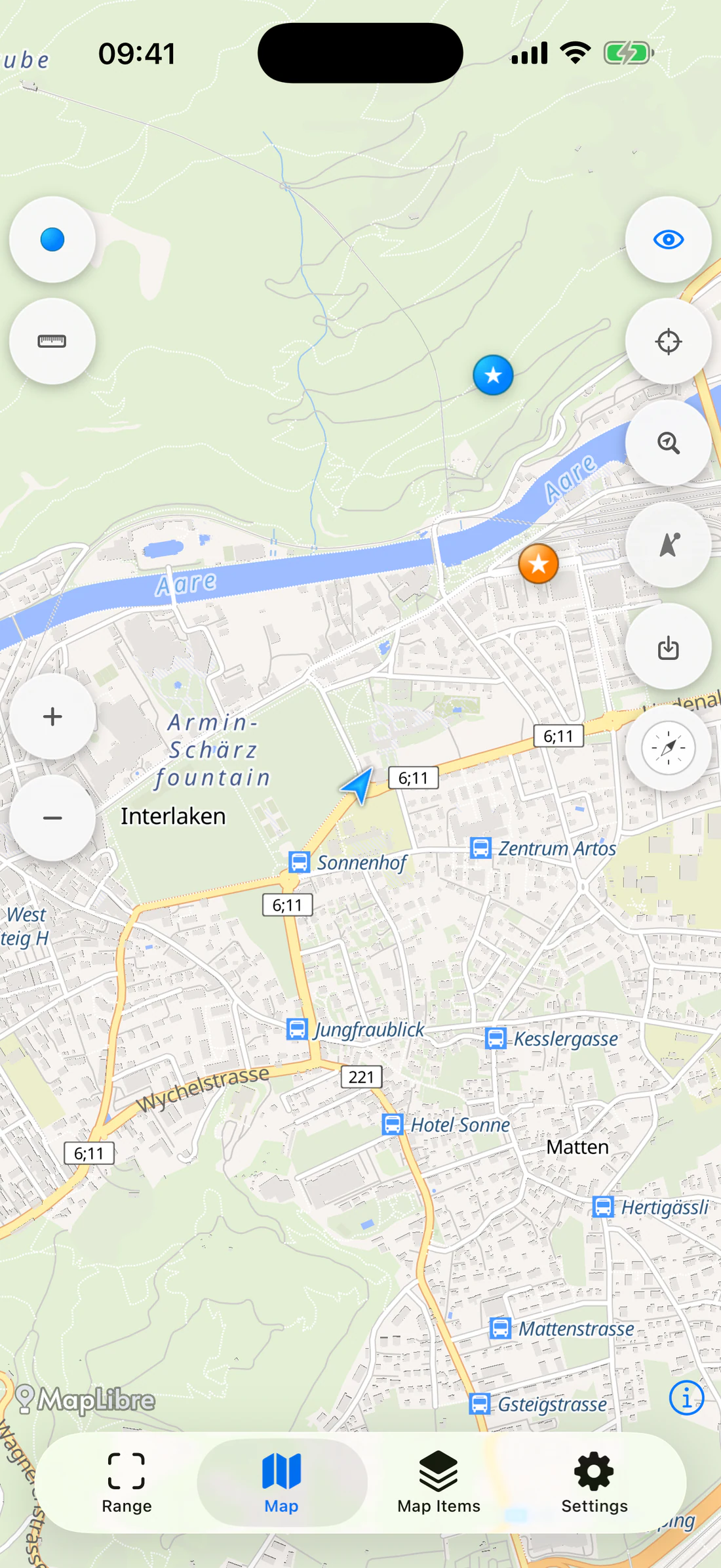
The tool column provides:
Add Waypoint at the current map center.
Measurements to create and edit map geometry.
Show/Hide Downloaded Areas.
Coordinate Inspector with a fixed center crosshair.
Coordinate Search.
Waypoint Tracking distances and lines.
Return to Current Location when the location arrow is outside the
visible region.
Download Area when the selected source supports it.
Map Compass.
Zoom In/Out.
Annotate every map control and the blue location arrow.
Pan with one finger, pinch to zoom, and rotate with the standard map gesture.
When the map is rotated, use the north/rotation control to return to north-up.
Current location
The current coordinate is drawn with the standard blue directional arrow.
When it leaves the visible region, a return-to-location control appears. Tap it
to center the map on the best current user coordinate.
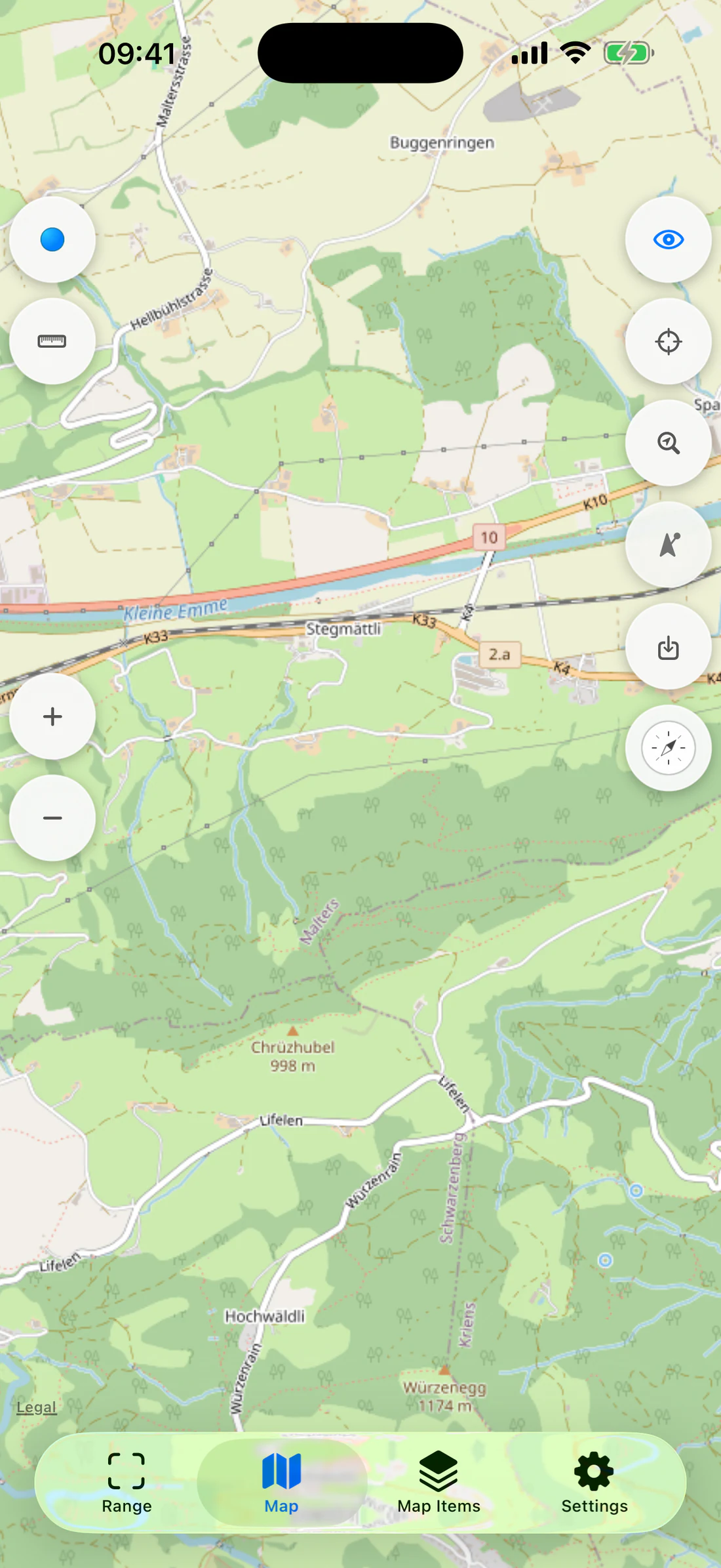
Pan away from fixture location; show return-to-current-location blue arrow control.
If current location quality becomes poor after a good fix, the app can retain
the last good coordinate for continuity. A warning indicator distinguishes
remembered data from a fresh fix. Never describe the remembered coordinate as
current.
In Map Compass mode, the compass presentation supplies its own current-location
context, so the normal location indicator is not duplicated inside the compass
map.
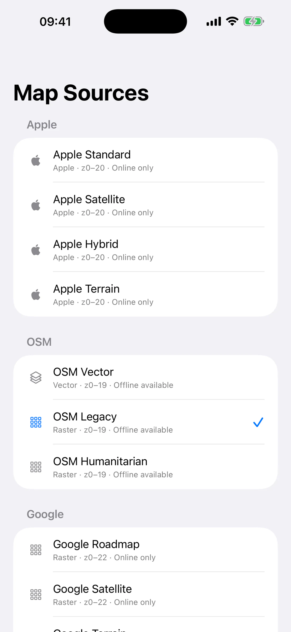
Choose a map source
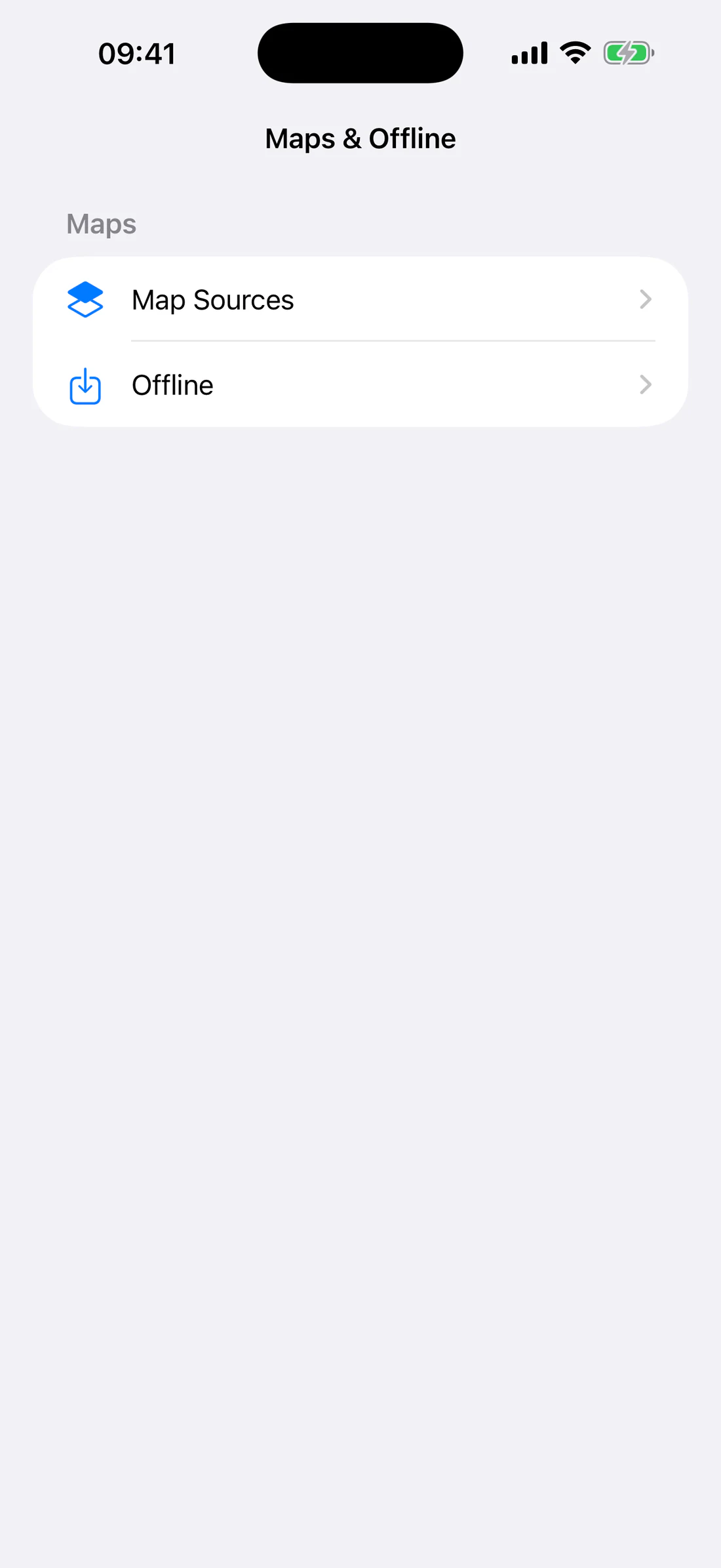
Open Map Items → Map Sources or the corresponding Maps & Offline settings
entry. Tap a row to select it. Each row identifies:
Apple, Raster, or Vector renderer;
supported zoom range;
online-only or offline availability;
selection checkmark.
Map Sources with visible release categories; no Premium accounts.
Sources visible in this release
The following table reflects the current provider catalog. Provider endpoints
and terms must be rechecked immediately before publishing the guide.
Category
Source
Renderer
Zoom
Offline
Apple
Apple Standard
Apple
z0–20
Online only
Apple
Apple Satellite
Apple
z0–20
Online only
Apple
Apple Hybrid
Apple
z0–20
Online only
Apple
Apple Terrain
Apple
z0–20
Online only
OSM
OSM Vector
Vector
z0–19
Available
OSM
OSM Legacy
Raster
z0–19
Available when current source policy permits
Google
Google Roadmap
Raster
z0–22
Online only in this release
Google
Google Satellite
Raster
z0–22
Online only in this release
Google
Google Terrain
Raster
z0–22
Online only in this release
Google
Google Hybrid
Raster
z0–22
Online only in this release
Cycling
CyclOSM
Raster
z0–20
Available
Hiking
Freemap.sk Outdoor
Raster
z0–20
Available
Hiking
OpenTopoMap
Raster
z0–17
Available
Hiking
Kompass OSM
Raster
z0–20
Available
OSM
OSM Humanitarian
Raster
z0–19
Available
Streets
Carto Positron
Raster
z0–19
Available
Streets
Carto Dark
Raster
z0–19
Available
Streets
Carto Voyager
Raster
z0–19
Available
Satellite
Esri Imagery
Raster
z0–20
Available
Nautical
OpenSeaMap
Raster overlay
z0–17
Available
Satellite
NASA City Lights
Raster
z0–8
Available
Legacy
Legacy USGS Topo
Raster
z0–20
Available
Legacy
Legacy USGS Imagery Only
Raster
z0–20
Available
FAA
FAA VFR Sectional
Raster
z8–12
Available
FAA
FAA VFR Terminal Area
Raster
z10–12
Available
FAA
FAA IFR Low
Raster
z7–12
Available
FAA
FAA IFR High
Raster
z5–9
Available
“Available” means the app is configured for user-initiated offline storage.
Actual downloads remain subject to provider response, current policy, source
caps, storage quota, network availability, and free device space.
Special source behavior
OSM Vector is rendered by MapLibre and permits map scale through zoom 19.
OpenSeaMap contains transparent nautical seamarks. It is drawn over OSM
Legacy, not over the Apple default map. Empty seamark tiles remain
transparent.
NASA City Lights is a low-zoom research/satellite layer and ends at z8.
FAA charts have deliberately restricted zoom ranges matching their
services.
Apple sources cannot be downloaded by RangeFinder.
Google downloads are hidden/unavailable in this release.
MapTiler and MapBox account/source rows are premium-only implementation and
must remain absent while premium features are hidden.
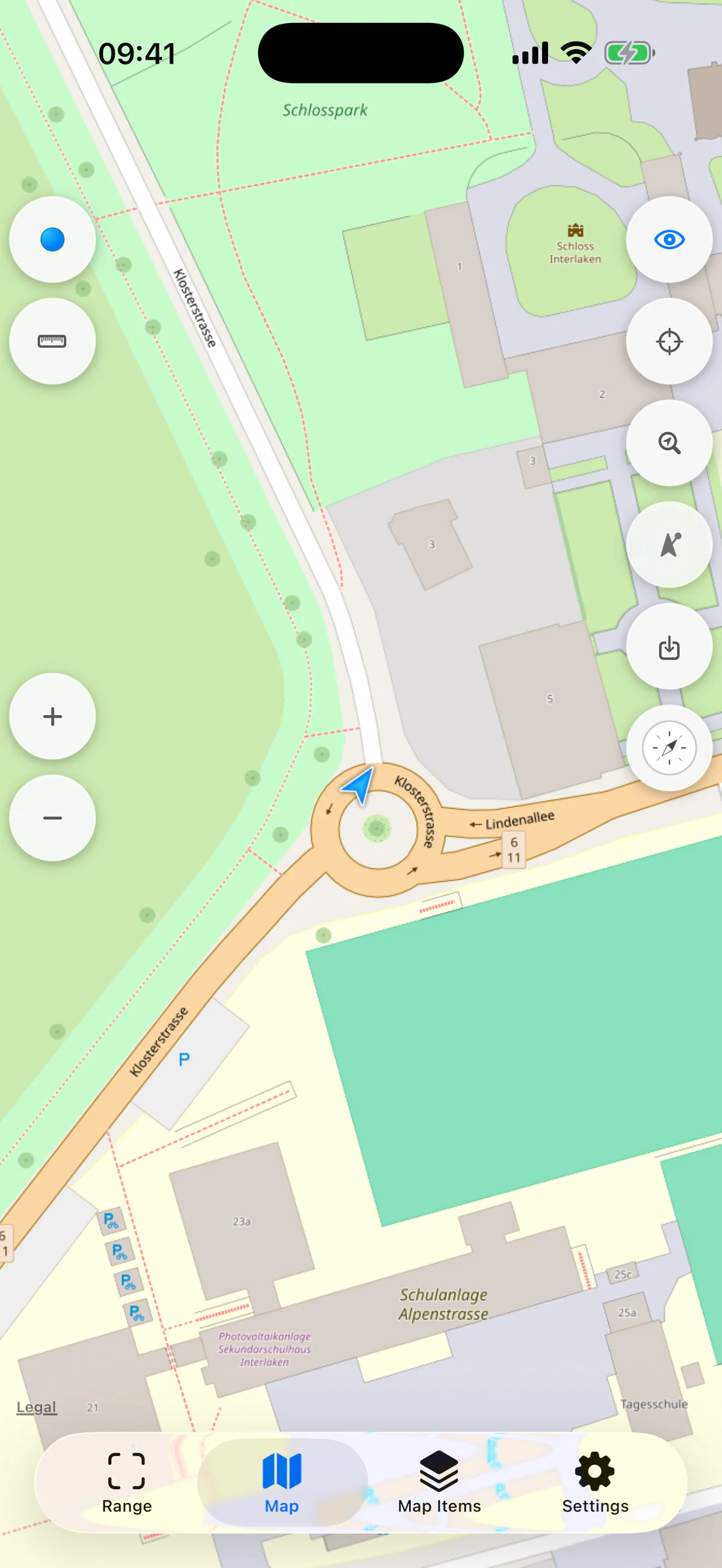
OSM Vector at high zoom with vector details.
Comparable raster source at the same region/zoom.
Coastal fixture with seamarks over OSM base, not Apple map.
Attribution and limitations
Map-source rows no longer include a separate Attribution settings section, but
provider attribution and terms remain part of the source configuration and
must be respected in the map and published documentation. Aeronautical,
nautical, satellite, and research layers are informational and may be stale,
incomplete, unavailable, or unsuitable for safety-critical navigation.
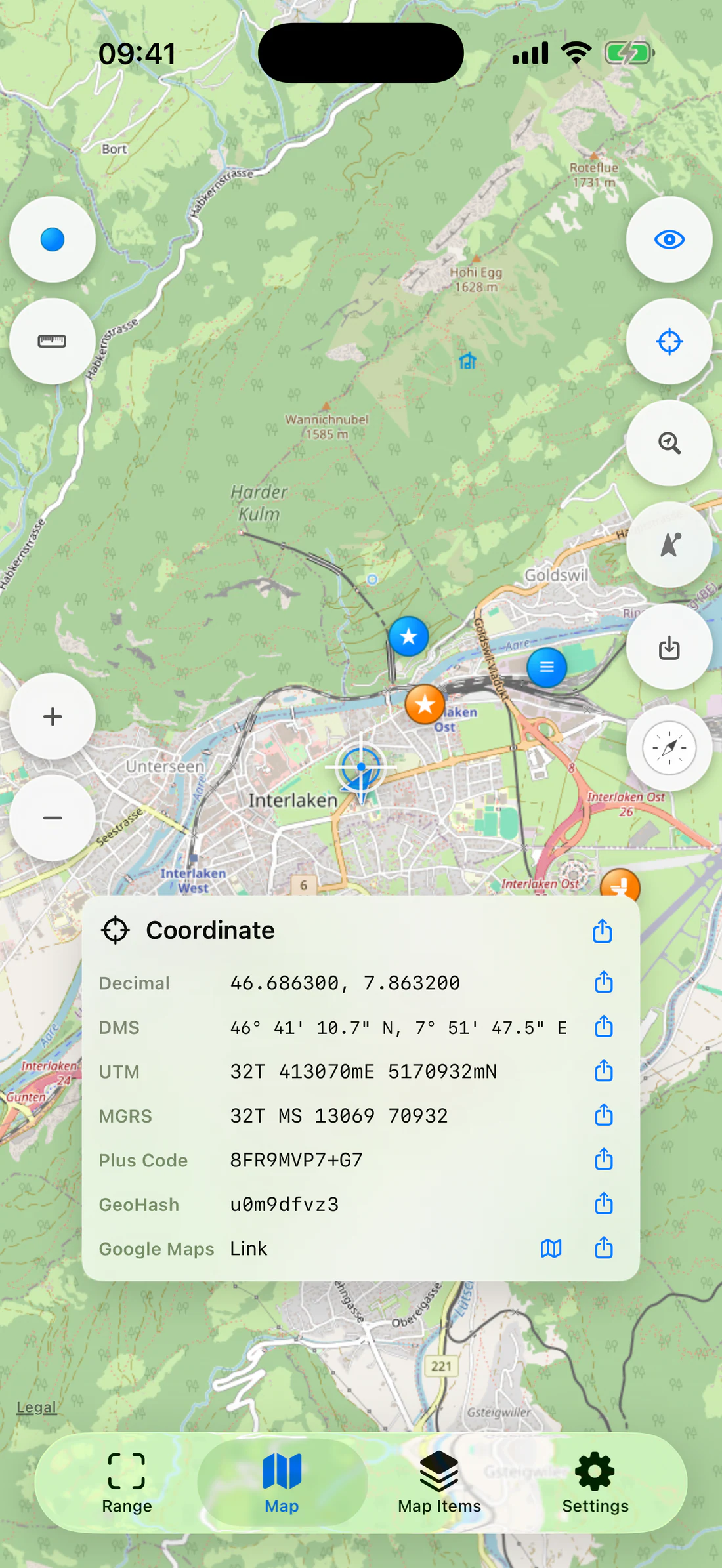
Inspect the map-center coordinate
Tap Coordinate Inspector.
Move the map under the fixed center crosshair.
Read the center coordinate card.
Use text selection or the Share button for an individual format.
Share the complete set or open/share the generated Google Maps link.
Tap the inspector control again to close it.
Fixed center crosshair and coordinate card.
The preferred coordinate format appears first, followed by the other supported
representations.
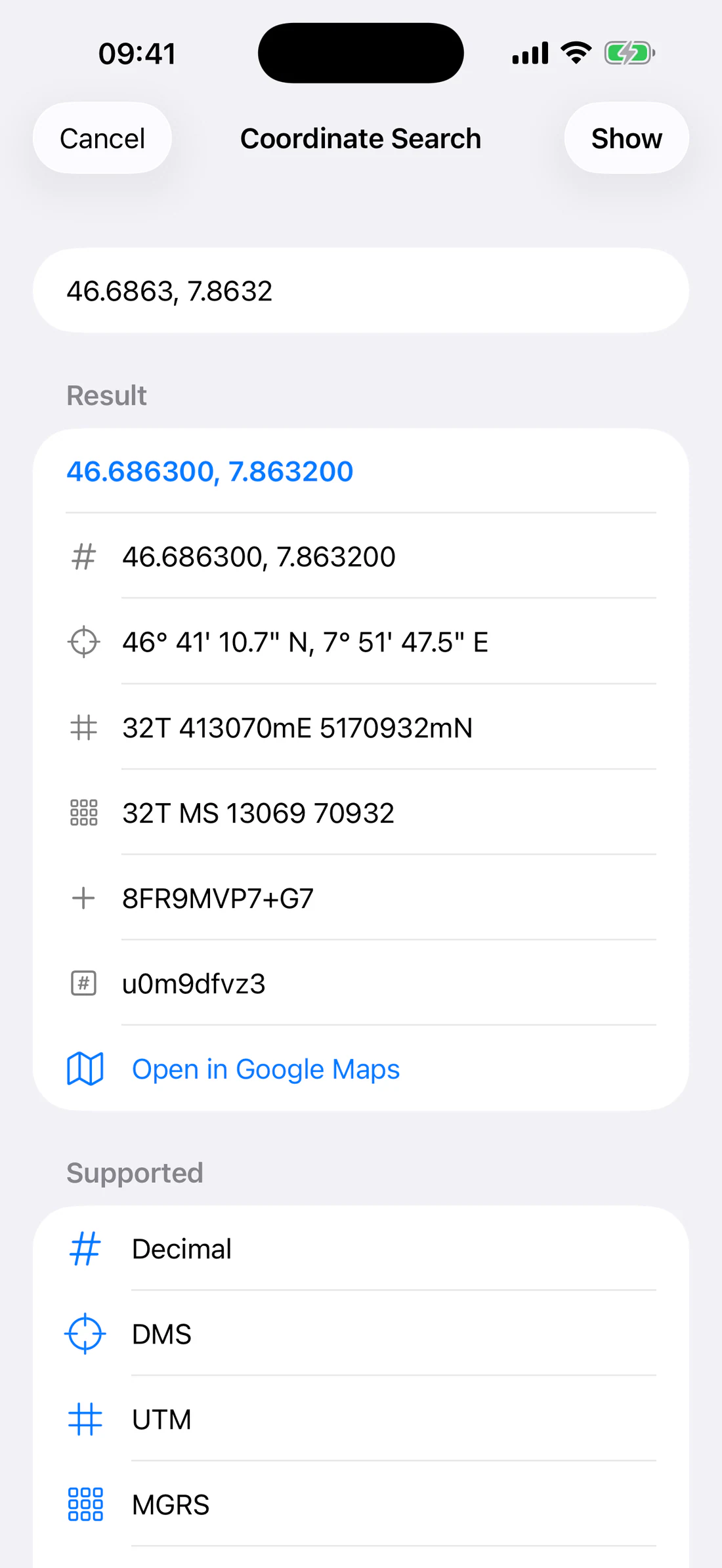
Search for a coordinate
Tap Coordinate Search.
Enter one of:
decimal latitude/longitude;
degrees, minutes, seconds (DMS);
UTM;
MGRS;
Plus Code;
GeoHash.
Review the parsed result and alternate representations.
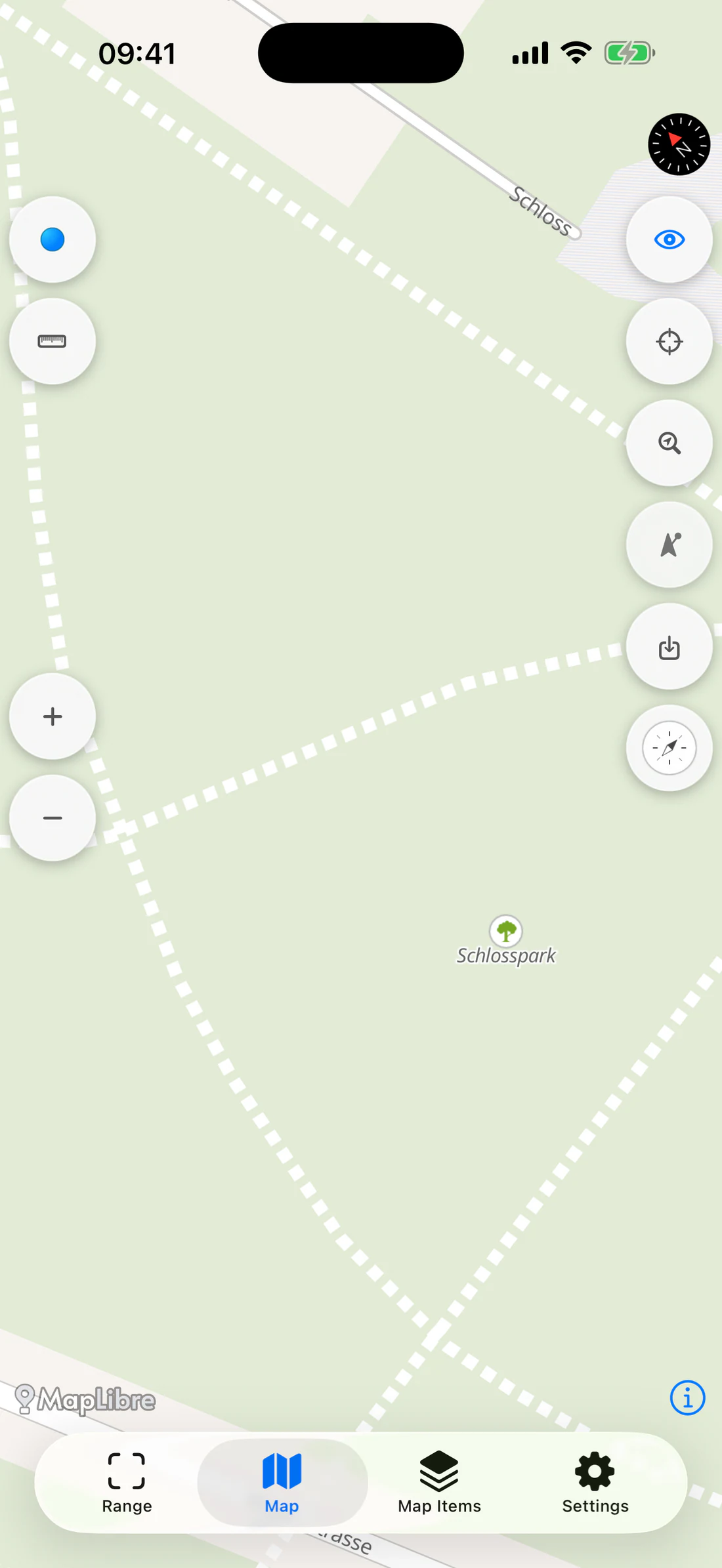
Tap Show or the result row.
The map centers on the coordinate and opens the inspector.
Search form with a valid coordinate and parsed result.
An unrecognized value shows Coordinate Not Recognized instead of guessing.
The result sheet can also open the coordinate in Google Maps without changing
the selected RangeFinder base map.
Preferred coordinate representation
Open Settings → Units & Coordinates and choose the preferred format. The
choice affects inspector, search-result ordering, waypoint fields/readouts, and
other coordinate displays. Internally stored latitude/longitude does not lose
precision merely because a different display format is selected.
Rotate the map with Map Compass
Normal map rotation follows touch gestures. In Map Compass, Rotate map with
compass continuously aligns the map with changing device heading while
preserving the current zoom. Disable it for a stable north-up map beneath the
dial.
Rotate map; show standard rotation/north-reset icon.
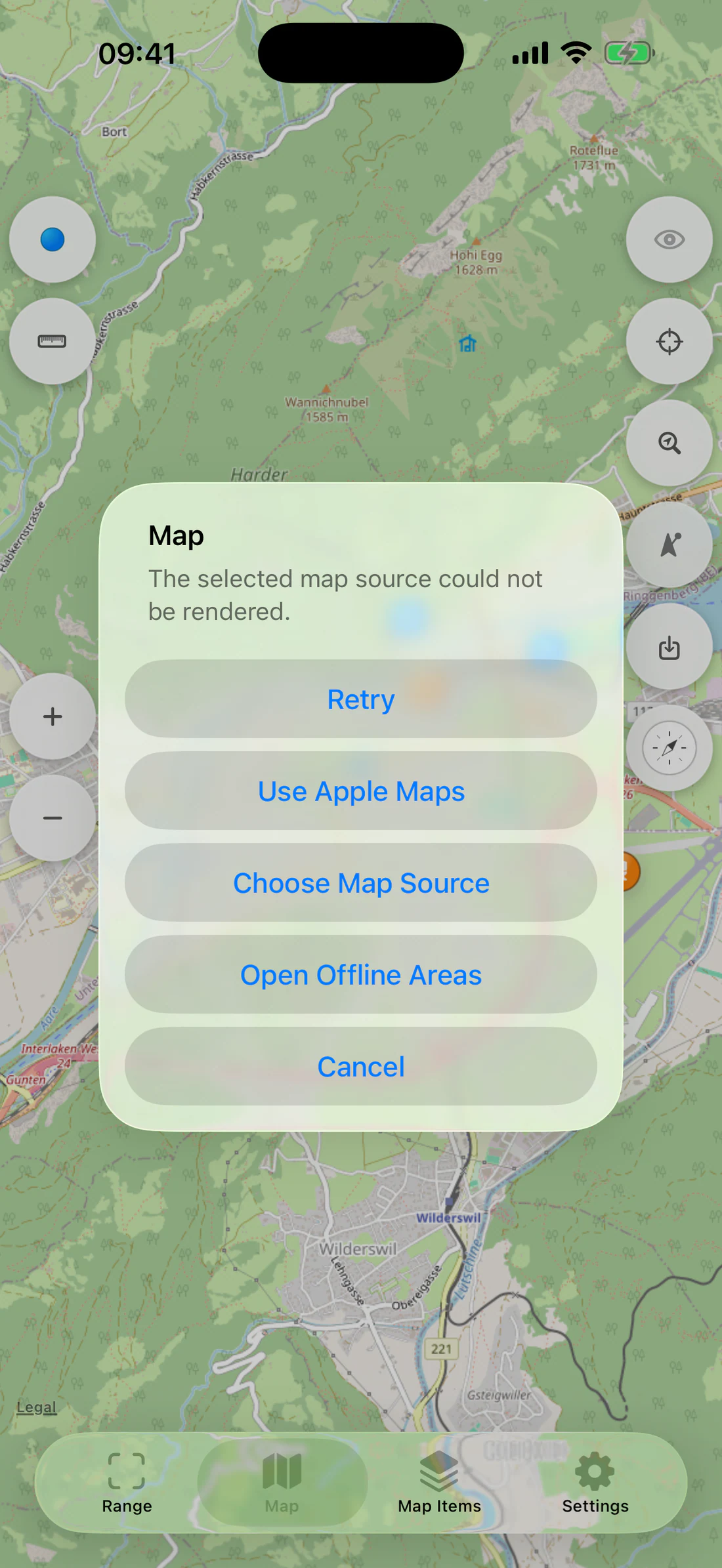
Map recovery
If restoring a source fails, the recovery alert can:
Retry;
use Apple Maps;
choose another Map Source;
open Offline Areas;
cancel and retain the current context.
Choose another source when a provider endpoint is unavailable. Do not clear all
offline data merely to recover one online provider.
Recoverable map error with Retry, Use Apple Maps, Choose Map Source, Open Offline Areas.
Offline maps
Offline Areas save supported vector resources or raster tiles for a selected
map region. Apple sources and Google sources are online-only in this release.
Before downloading
Select an offline-capable source.
Use Wi-Fi for a large area when practical.
Confirm sufficient RangeFinder quota and at least the required free device
space.
Start with the smallest useful region and maximum zoom.
Read the provider notice.
Save an area
Open Map.
Select an offline-capable map source.
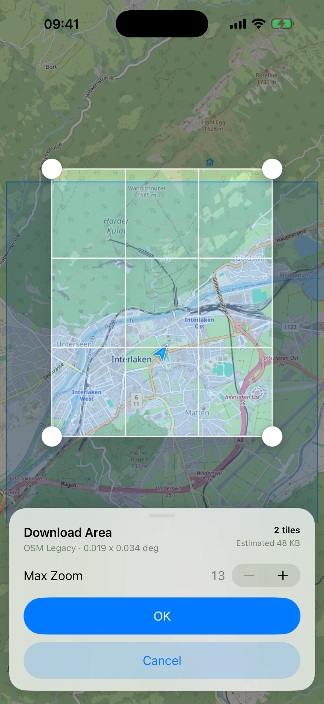
Tap Download Area.
Pan to position the selection rectangle.
Drag/resize the selection as needed.
Choose the maximum zoom.
Review tile/resource count, estimated size, source, bounds, and notice.
Confirm the download.
The app opens Offline Areas.
Monitor progress; pause or resume when available.
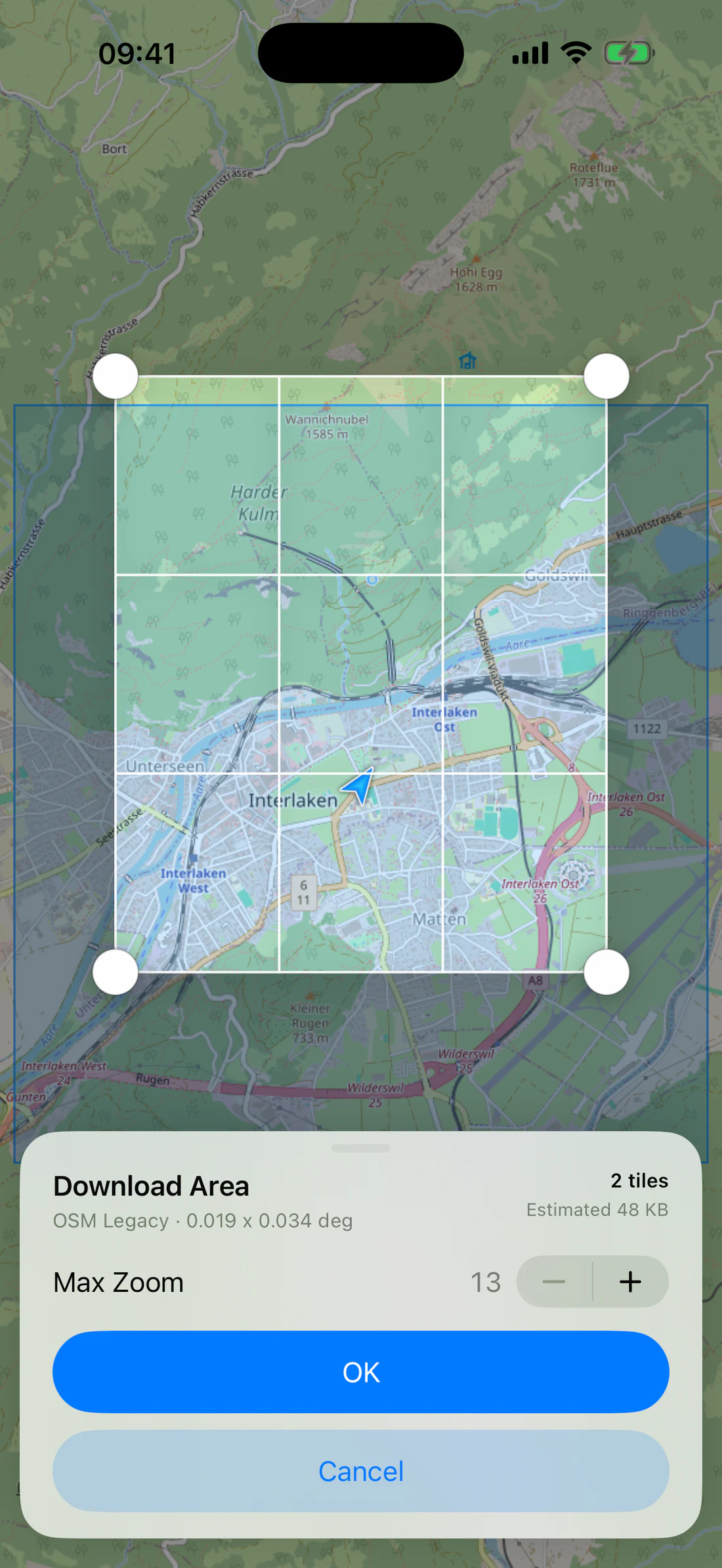
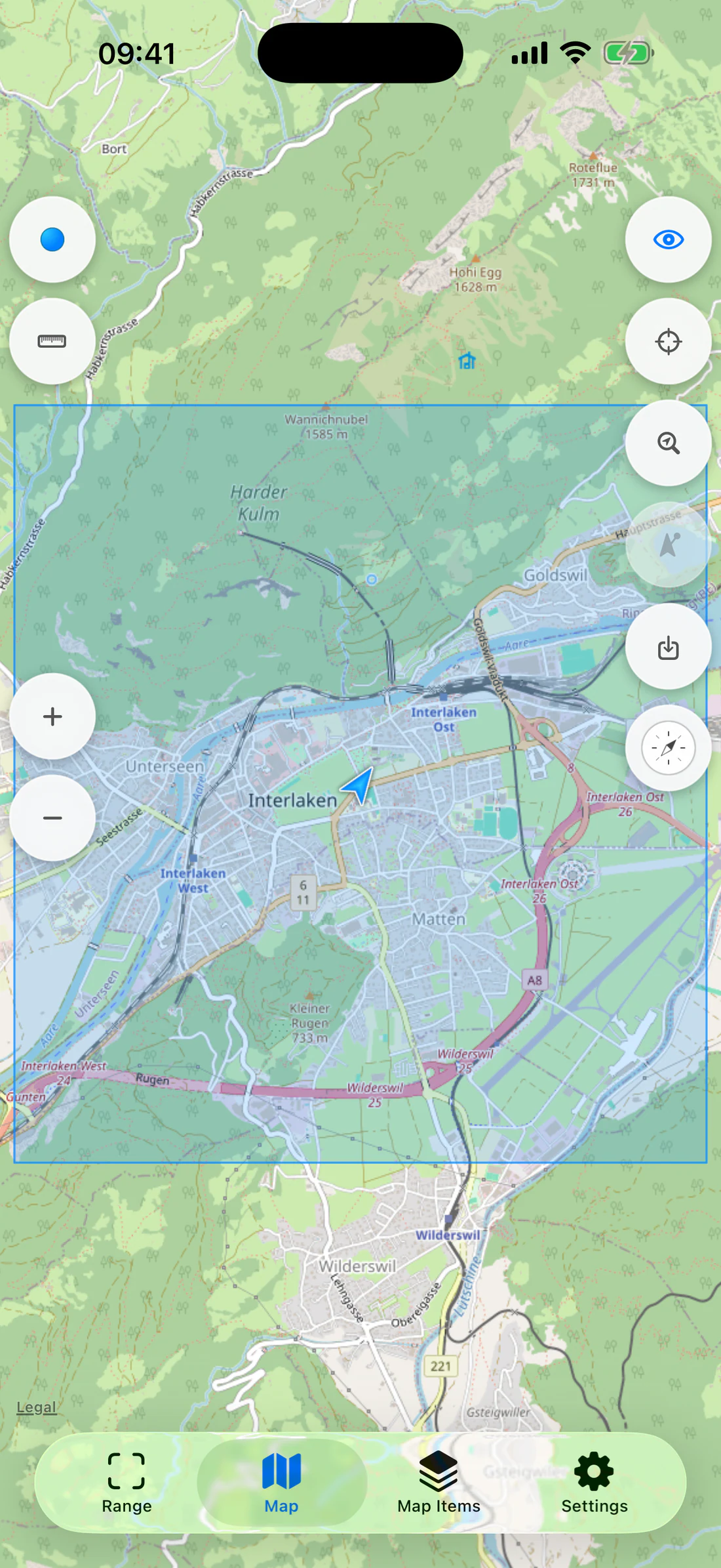
OSM selection rectangle with all four handles and underlying map visible.
Maximum Zoom controls, tile/resource count, estimated bytes, source name.
Higher zoom increases resources rapidly because every additional zoom level can
subdivide each visible tile into four children.
Example: Interlaken fixture
Use OSM Vector near 46.686300, 7.863200.
Frame the town and one nearby trail.
Compare a maximum zoom of 13 with a higher value.
Reduce the bounds if the high-zoom resource estimate is unnecessary.
Download.
Turn on airplane mode and verify the saved area at every zoom you intend to
use.
Storage and tile limits
State
Offline quota
Per-area tile limit
Initial
512 MiB
8,000 tiles
After first completed offline map bonus
1 GiB total
16,000 tiles
RangeFinder also preserves a 2 GiB free-space reserve on the device. A
source-specific request cap may lower the effective tile limit.
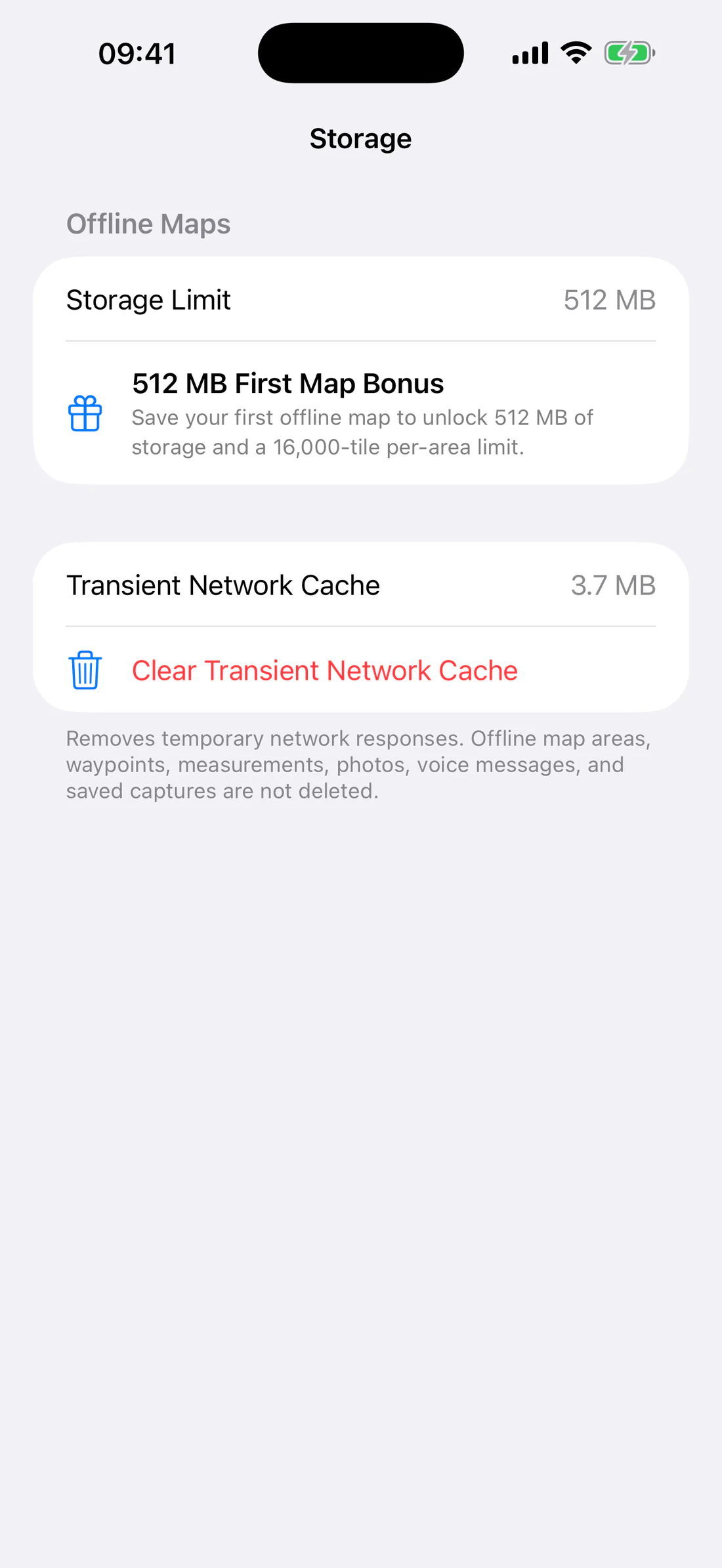
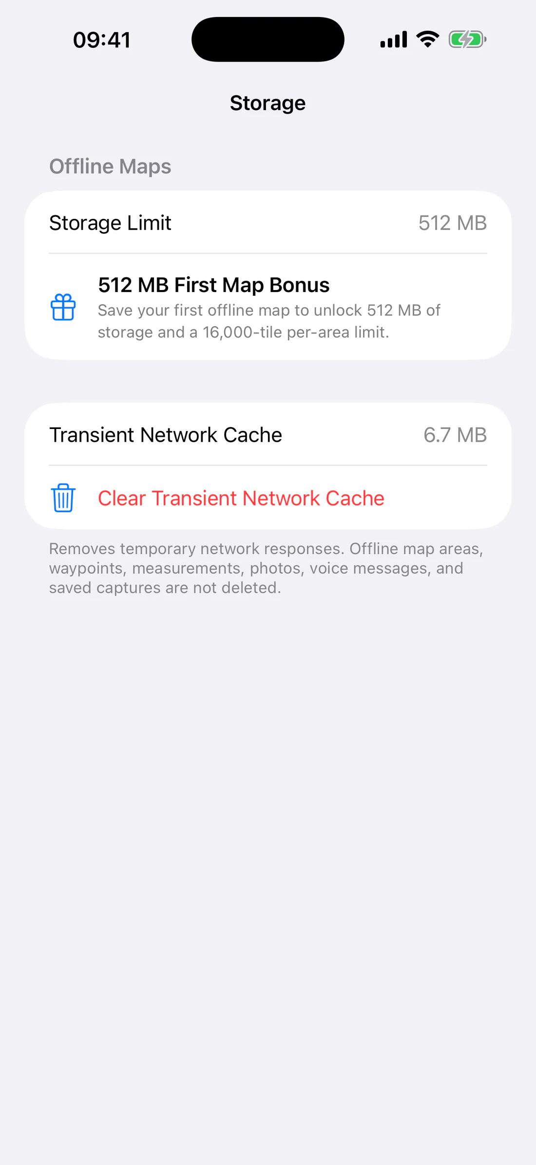
Settings → Storage before bonus: 512 MB and gift outline.
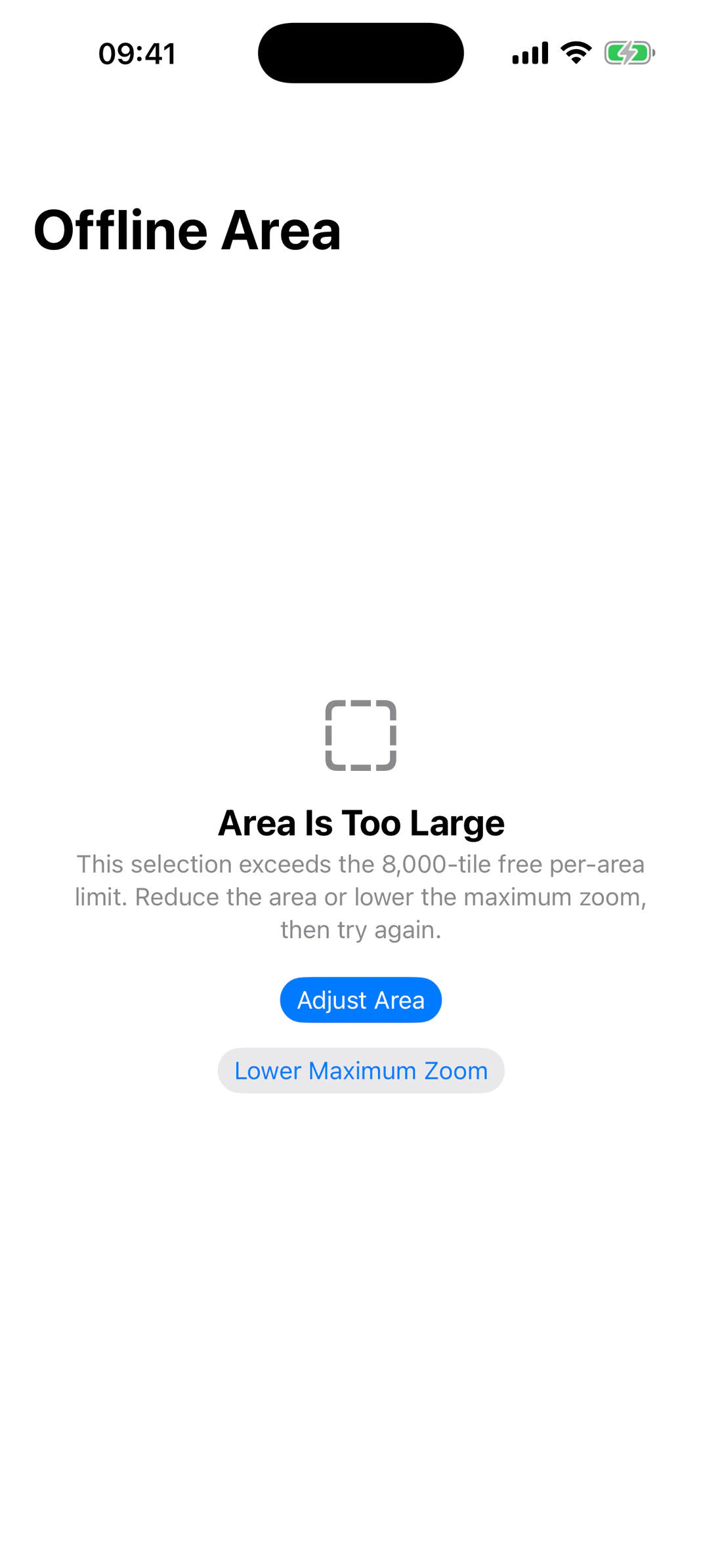
Area exceeding tile/quota limit with actionable correction.
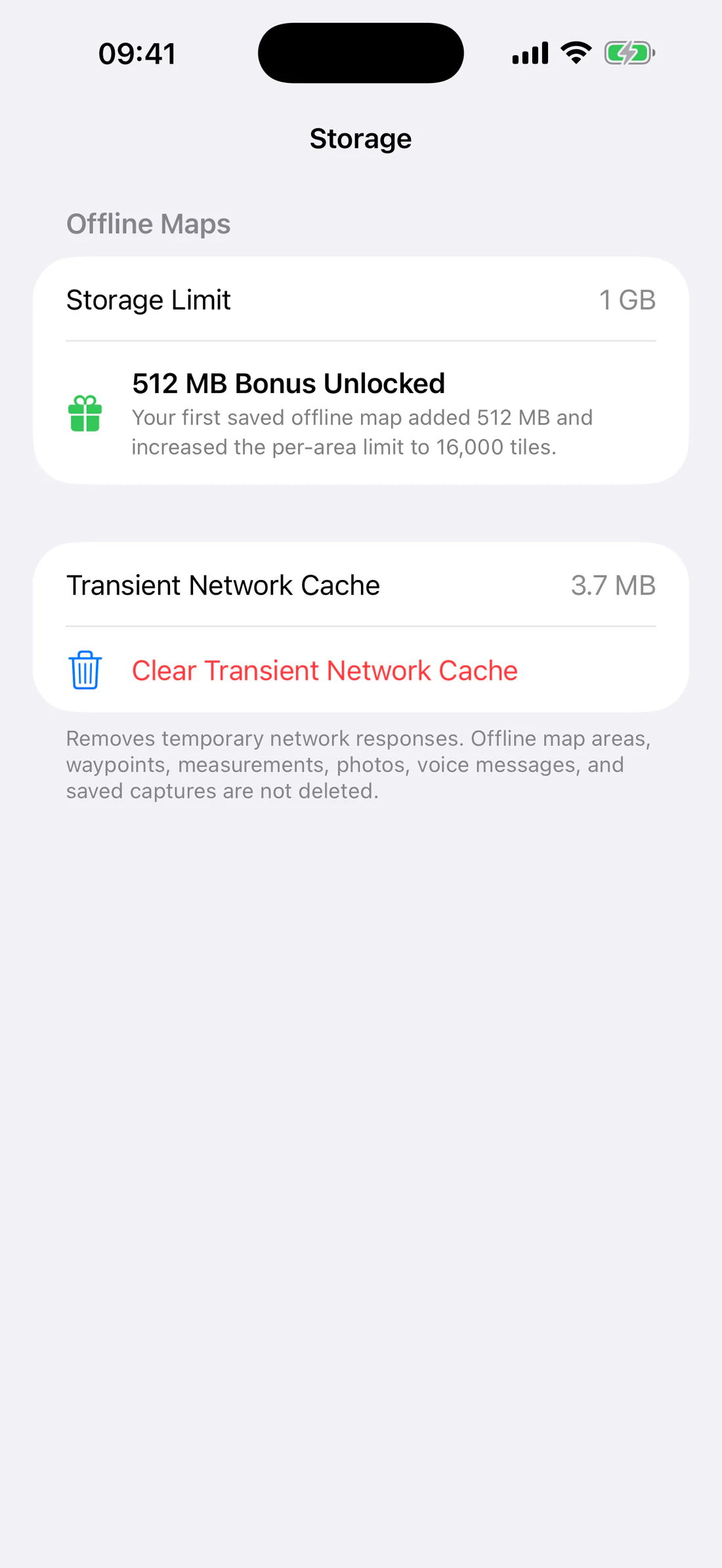
When the first area completes successfully, RangeFinder awards an additional
512 MiB and raises the per-area limit from 8,000 to 16,000. The bonus alert
explains the new total and has a standard blue-tinted OK action.
After first completed area: 1 GB, filled gift, 16,000-tile explanation.
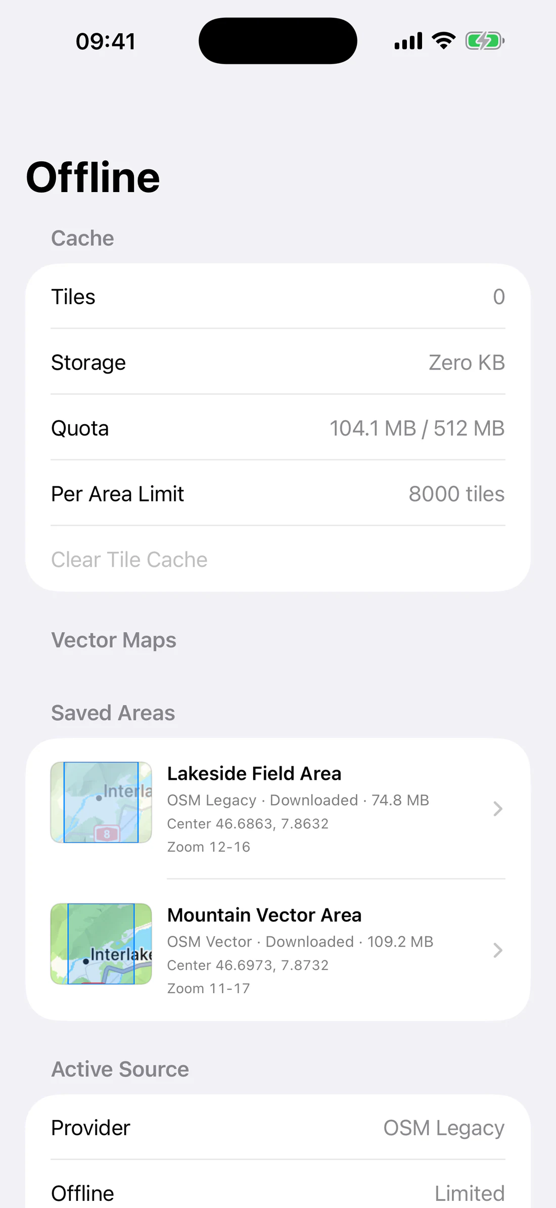
Offline Areas list
Open Map Items → Offline Areas or Settings → Maps & Offline → Offline.
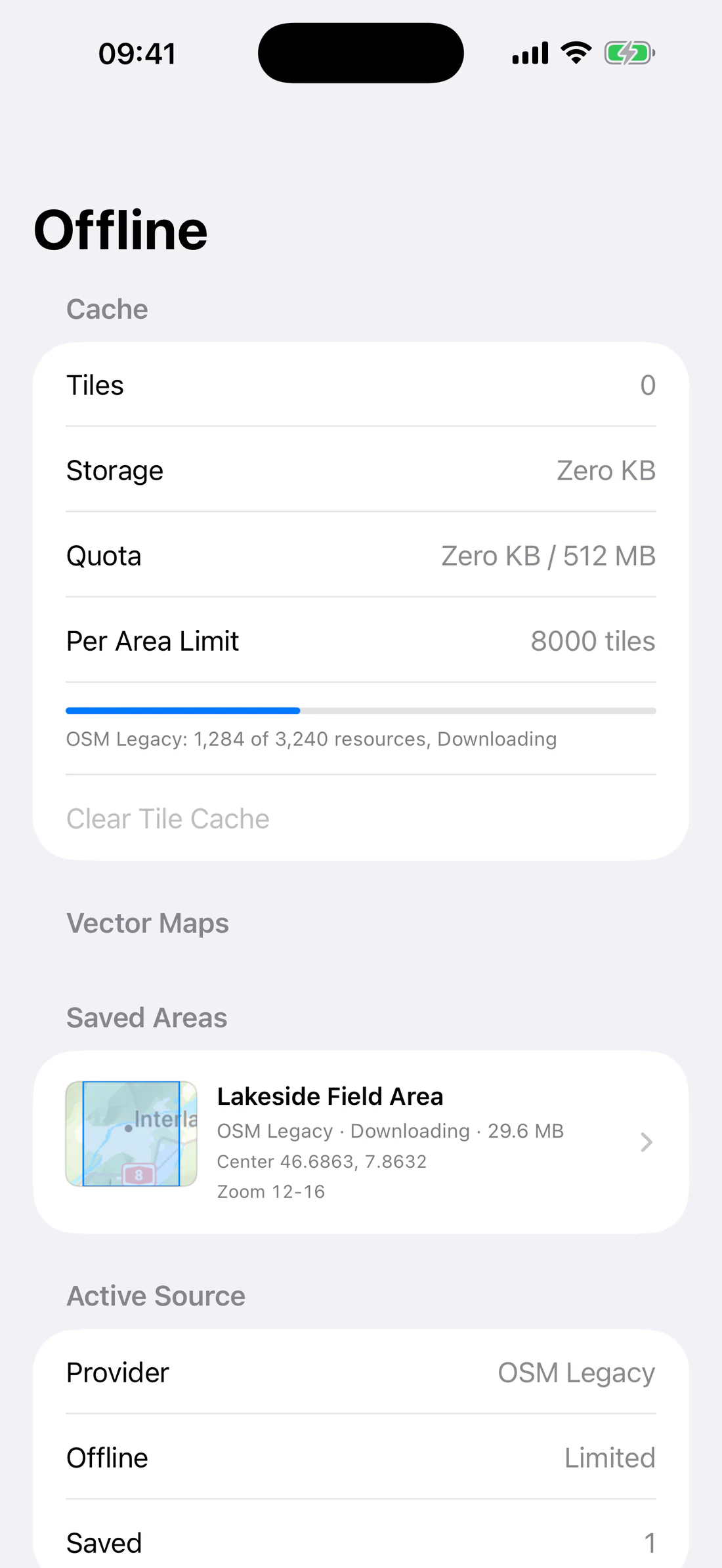
Each saved item uses its actual area thumbnail and can show:
name;
provider;
geographic bounds;
minimum and maximum zoom;
raster tile count or vector-resource progress;
estimated and actual bytes where available;
downloading, paused, complete, or failed state.
Saved raster and vector areas with distinct thumbnails.
Manage an area
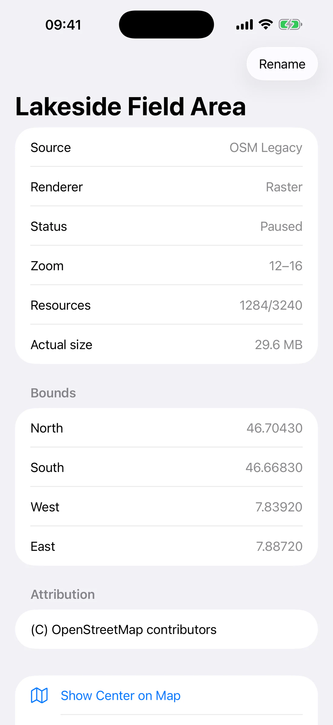
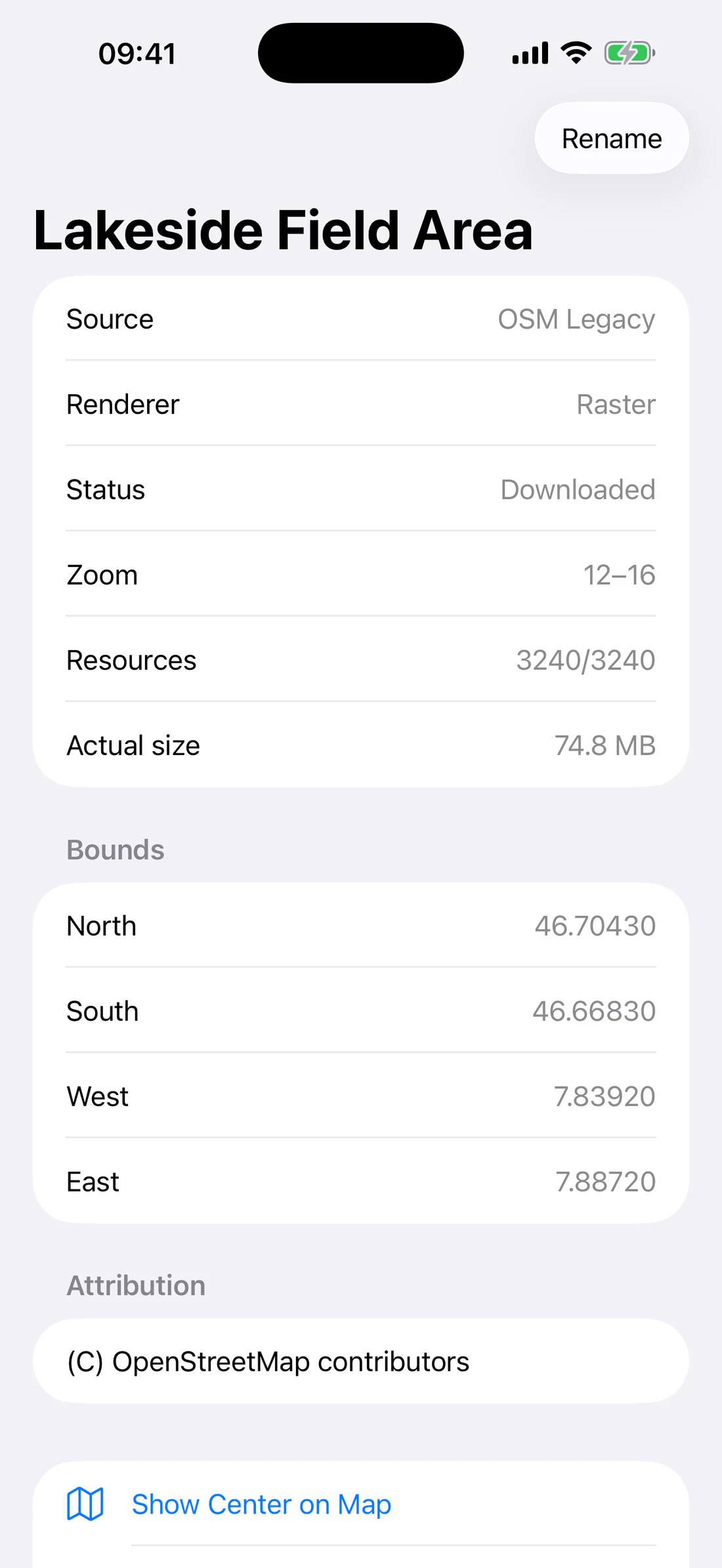
Open an area to:
rename it;
inspect source, bounds, zoom, and progress;
pause/resume an active raster download;
show its center on the map;
retry after failure;
delete it.
Active download with completed/total resources and state.
Paused area with Resume.
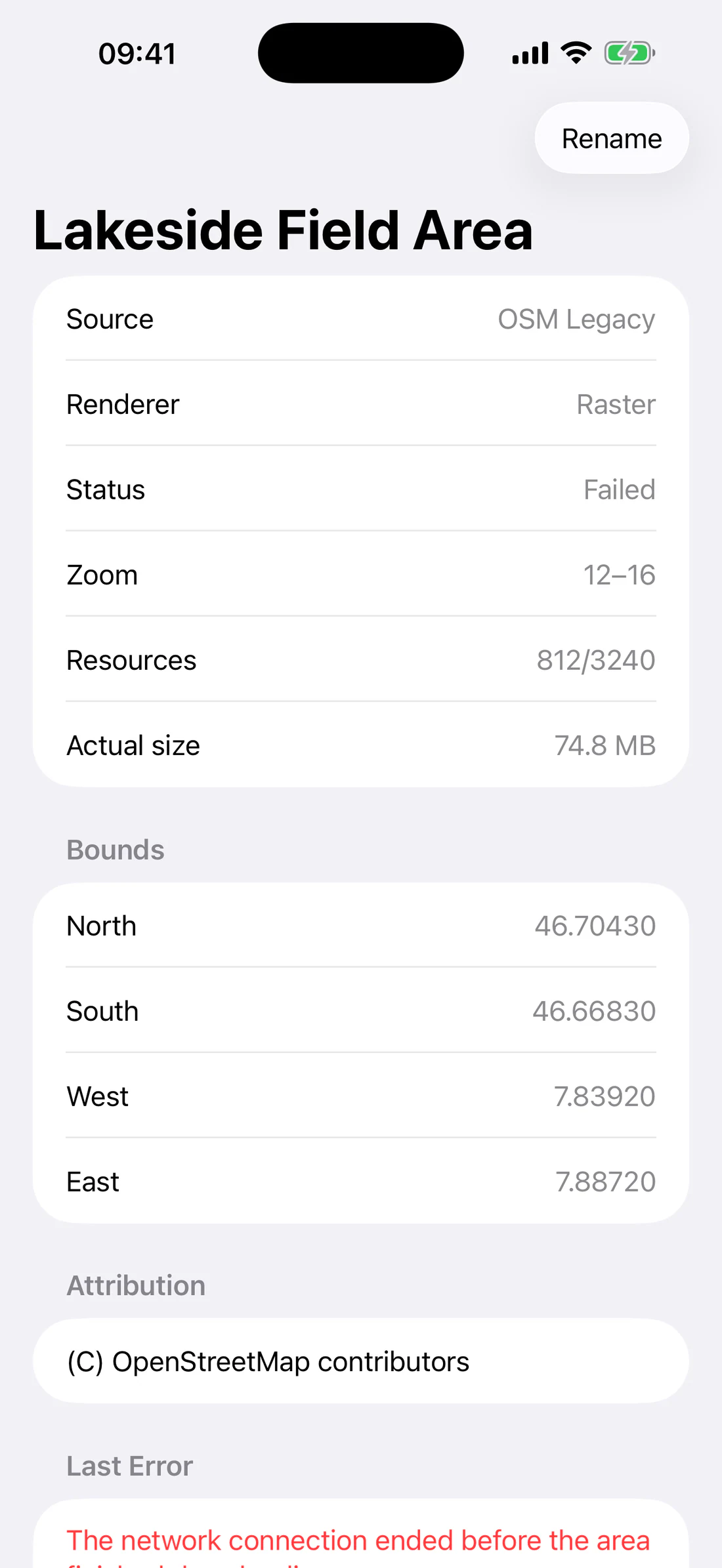
Area bounds, zoom range, attribution, Show Center, Rename, Delete.
Failed offline download with retry path.
Deleting a saved area removes its area record and resources that are no longer
shared. Shared raster tiles required by another saved area must remain
available.
Show downloaded-area outlines
Use the downloaded-area visibility control on Map to show or hide saved bounds
for the selected provider.
Return to Map with downloaded-area overlay visible, then derived comparison with it hidden.
The overlay is a planning aid; it does not prove that every tile/resource
inside the bounds finished successfully. Confirm the item state and test
offline.
Clear tile cache
Offline settings can clear downloaded raster tiles. This is destructive:
saved raster area records may remain but require download again. It does not
mean that Apple or Google content becomes available offline.
Troubleshooting
Download button is absent
The selected source is online-only or hidden by release policy. Choose an
offline-capable source.
The estimate exceeds the limit
shrink the area;
reduce maximum zoom;
choose a source with a smaller resource requirement;
complete the first small area to earn the documented bonus;
delete unneeded offline data.
Tiles blink while downloading
The renderer should retain the currently displayed tile until a replacement is
ready. If flashing persists, record provider, zoom, device, and whether the
tile was online, transiently cached, or downloaded.
An area works online but not in airplane mode
The visible online map may include transient resources outside the saved area
or beyond its maximum zoom. Return online, inspect the area state, retry
failures, and test within its exact bounds/zoom range.
Provider stops working
Provider endpoints and policies can change. Retry, choose another source, and
preserve existing offline data until the issue is understood.
Waypoints
A waypoint stores a geographic coordinate with a name, note, optional altitude,
icon, visibility, optional A/B role, and media attachments. The same selected
icon is used on the map, list, Range camera, and Map Compass.
Create a waypoint
RangeFinder provides five creation/import paths:
Long-press the map.
Tap Add Waypoint to use the current map center.
Open Map Items → Waypoints → Add → New Waypoint.
Open Map Items → Waypoints → Add → Create From Photo.
Import GPX from the Waypoints transfer menu.
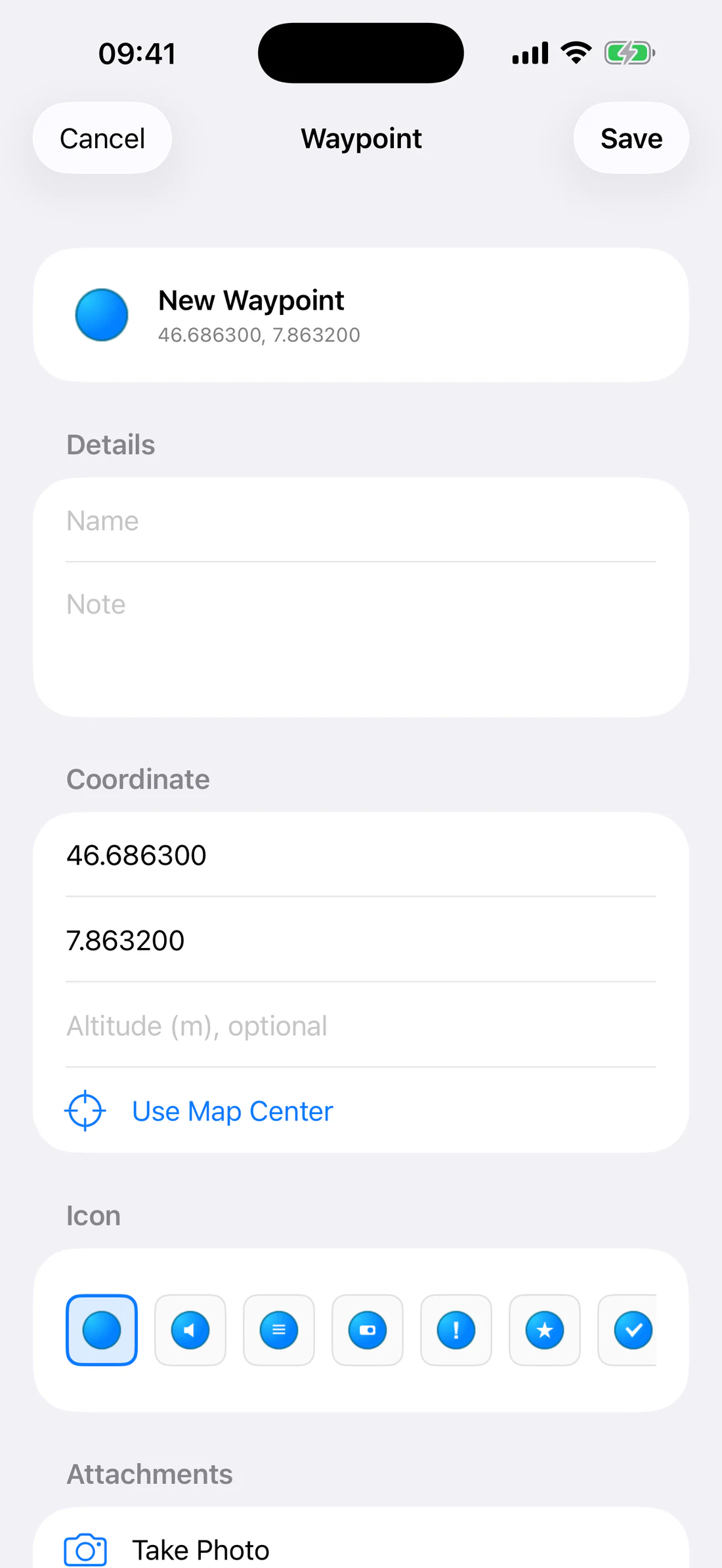
Long-press map at fixture coordinate and show new waypoint editor.
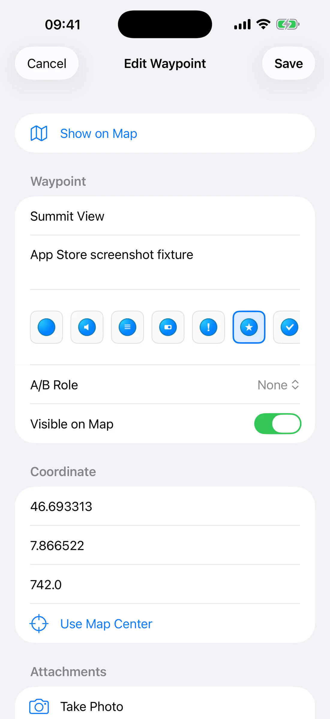
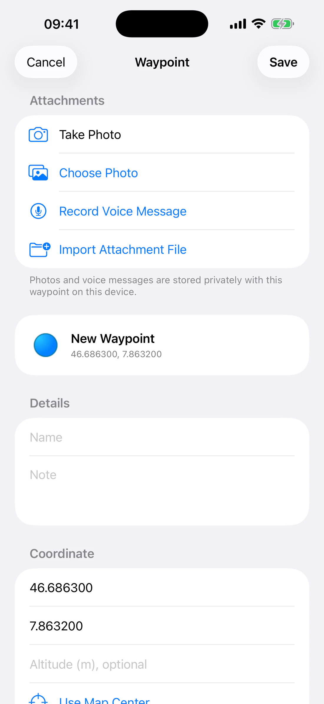
Edit waypoint fields
The editor includes:
Name;
Notes;
latitude and longitude;
optional altitude;
quick icon choices;
More icon grid;
A/B measurement role;
visible-on-map state;
attachments.
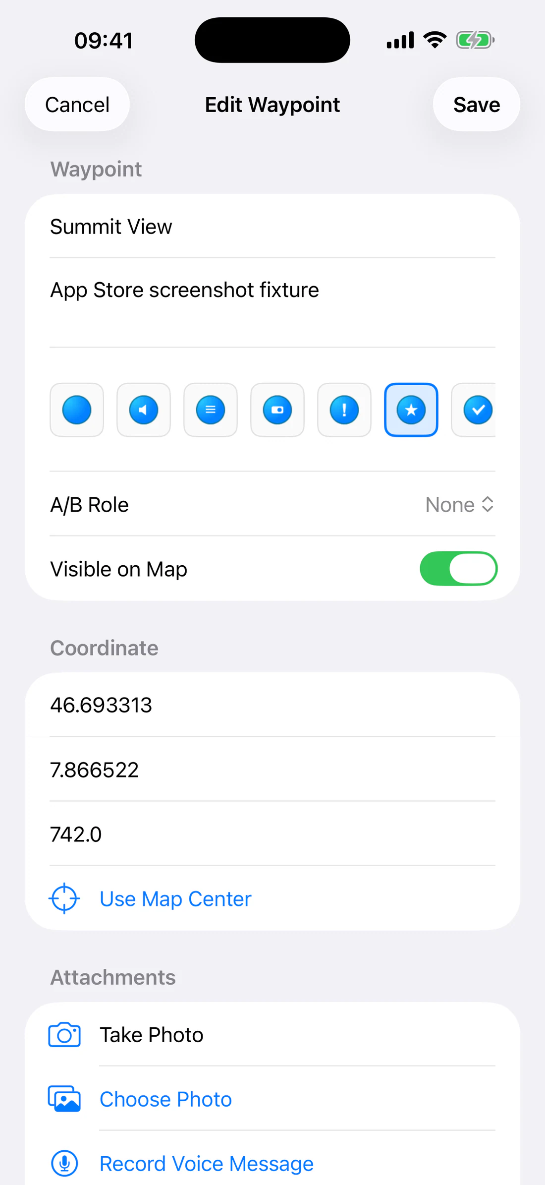
Complete editor with name, note, coordinate, altitude, icon, role, visibility.
Enter a descriptive name that will remain recognizable in a camera or compass
label. Verify coordinates before saving.
Choose an icon
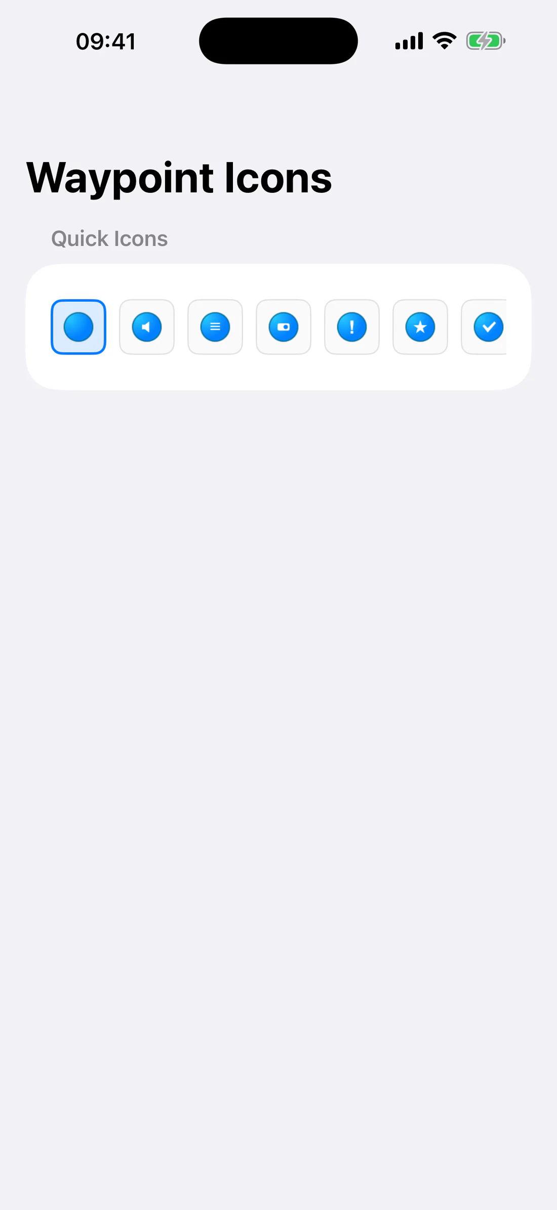
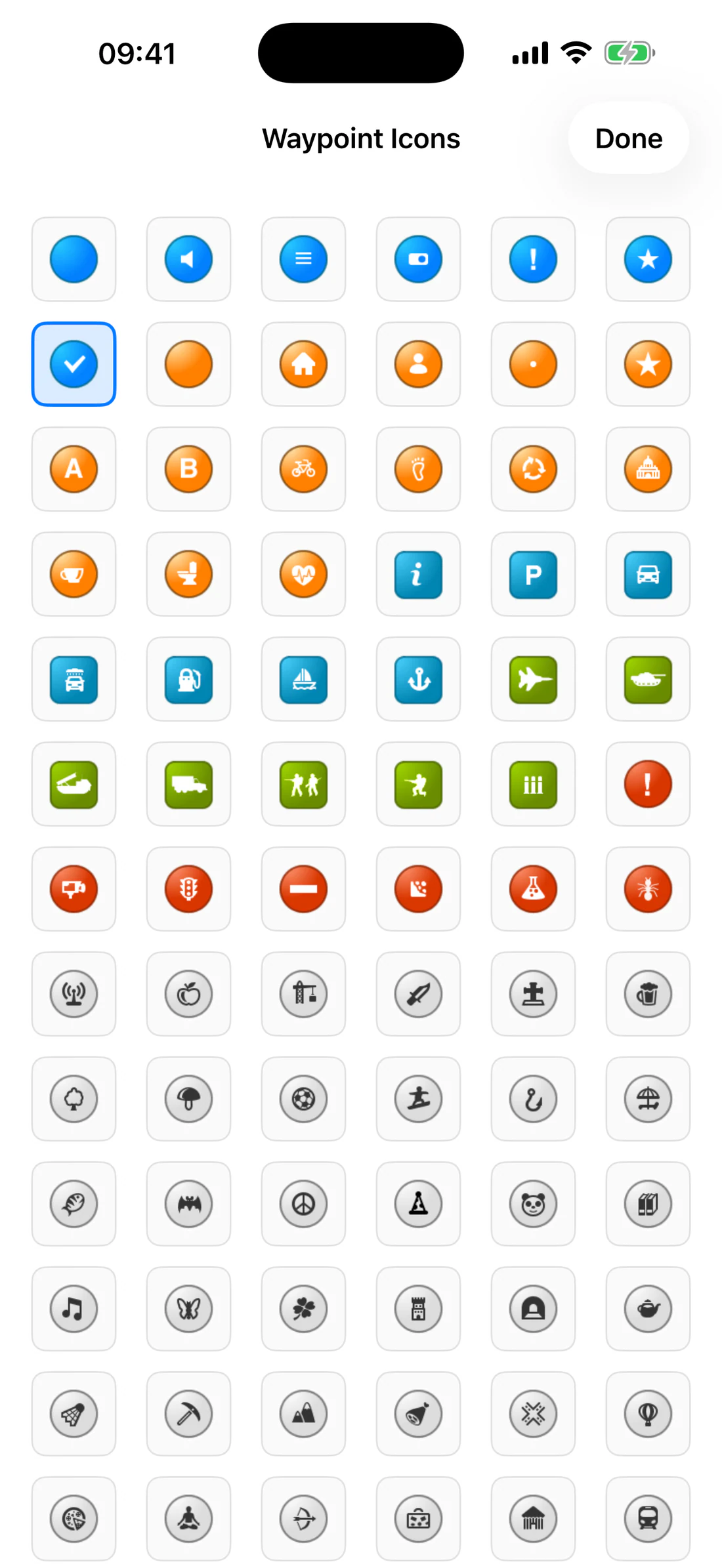
Seven quick icons are available in the editor. Tap More to browse the full
asset-catalog-backed waypoint icon library.
Seven quick icons.
More icon grid with selected icon/checkmark.
Icon selection is not merely decorative: it provides visual identity wherever
the waypoint is presented.
Control visibility with checkmarks
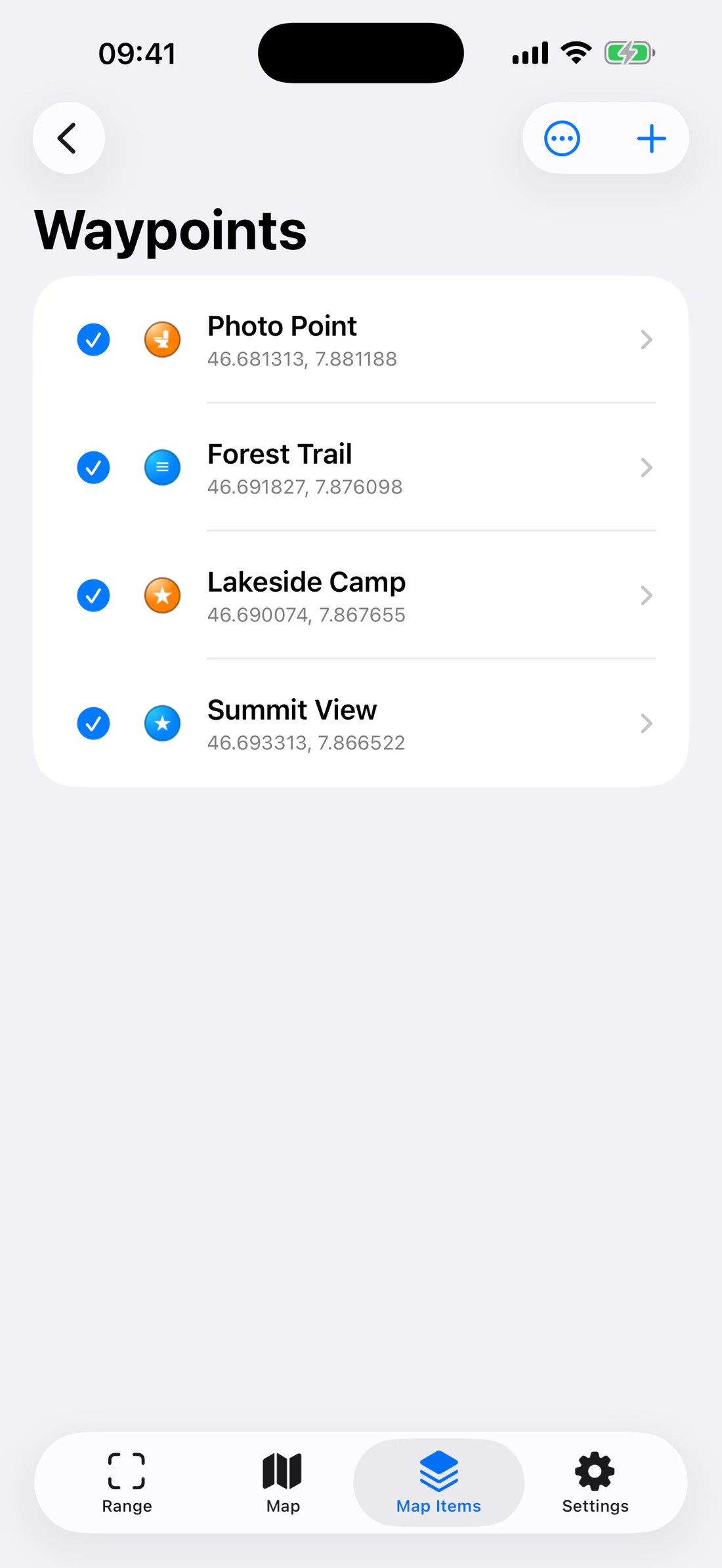
Open Map Items → Waypoints. Tap the circle/checkmark beside a row:
checked: visible on the map and eligible for Waypoints camera mode;
unchecked: hidden from those presentations.
List with visible and hidden checkmarks, icons, A/B badges, search.
Map Compass applies an additional selection layer: a waypoint must first be
checked in this main list, then included in Compass Settings.
Manage the list
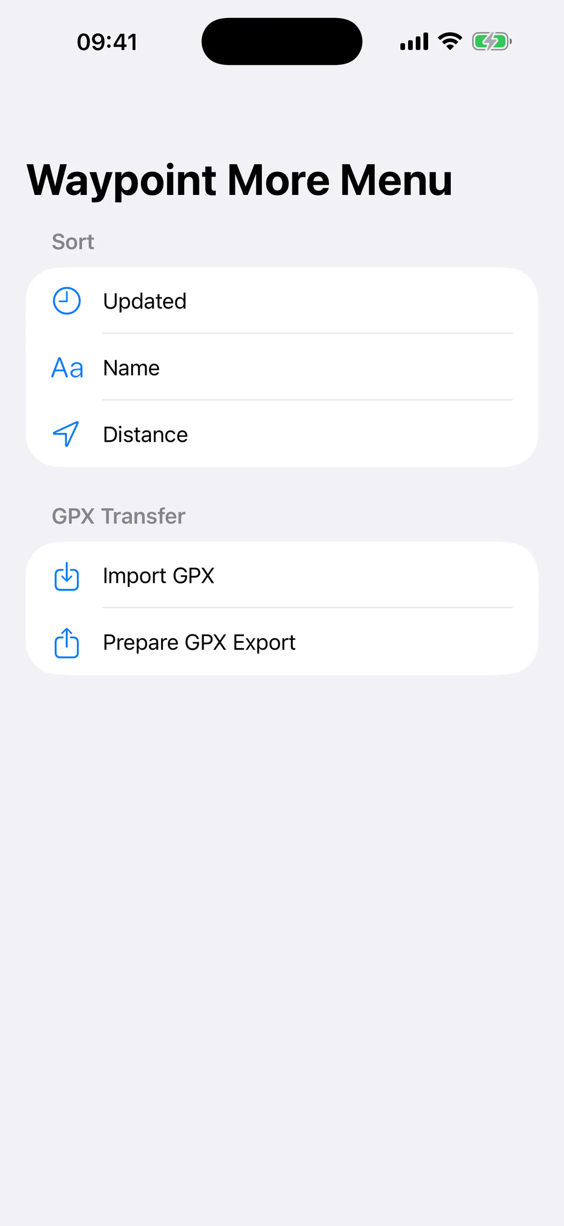
Use the waypoint list to:
search;
sort by updated time, name, or distance;
duplicate;
show on map;
edit;
delete with confirmation;
import/export GPX.
More menu with sort, GPX import, GPX export preparation.
Open an existing waypoint and choose Show on Map to center the map on it.
Edit existing waypoint and use Show on Map.
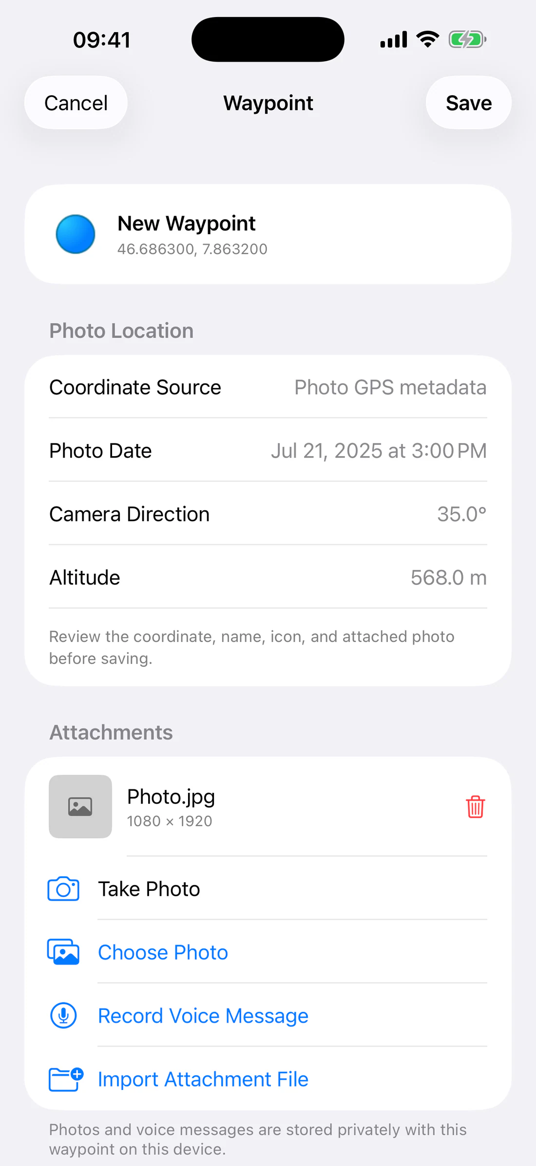
Create from a photo
Open Map Items → Waypoints.
Tap Add → Create From Photo.
Choose an image.
RangeFinder reads available metadata locally:
GPS latitude/longitude;
altitude;
capture date/time;
image direction.
Review the prefilled waypoint.
Edit name, note, coordinate, altitude, or icon.
Save.
The photo is attached to the waypoint after the draft is confirmed.
Create From Photo with GPS source, date, direction, altitude, attached thumbnail.
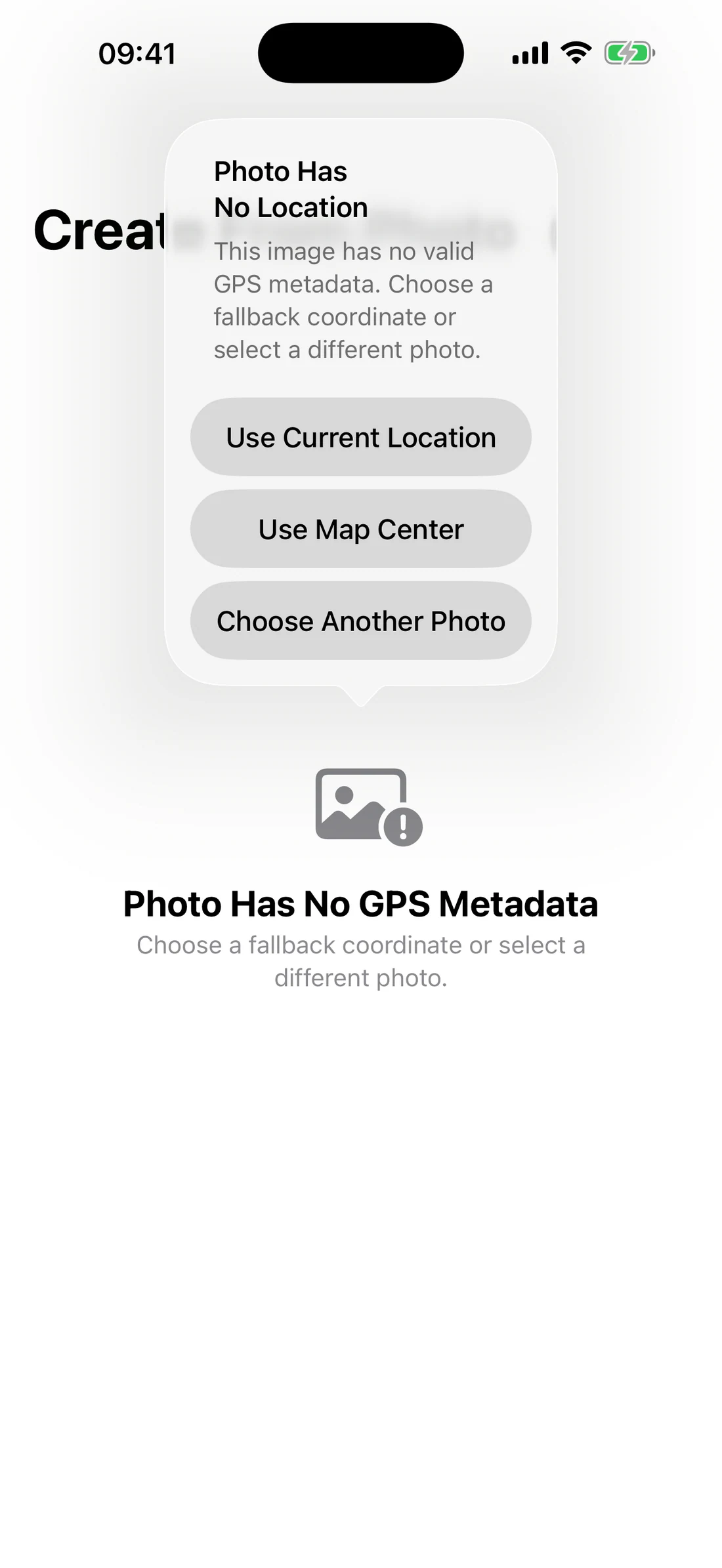
Photo without GPS
RangeFinder must not invent a coordinate. The fallback offers appropriate
choices such as:
current or remembered location, clearly identified;
current map center;
choose another photo;
cancel.
No-location dialog with Current Location, Map Center, Choose Another, Cancel.
Add photo attachments
In the waypoint editor/attachments section:
Choose Photo selects from Photos;
Take Photo uses the camera;
photo-file import accepts a compatible local file;
tapping an attachment opens its viewer;
Remove deletes the local waypoint attachment after confirmation.
Audio-file import can add an existing compatible file. If microphone access is
denied, open iOS Settings and allow it before recording again.
See waypoints through the camera
Result
Display checked waypoints as augmented camera labels containing icon, name, and
coordinate-based distance.
Create/import the waypoints.
Check the desired rows in Map Items → Waypoints.
Open Range.
Choose Waypoints.
Turn toward a target.
Read its name and geodesic distance.
Tilt the phone; labels move vertically with the projected camera horizon.
If a target leaves the field of view, follow its dot and label on the screen
border.
Camera waypoints use the current location and heading when valid. If a current
fix becomes poor, the last good coordinate may be retained with a warning so
labels do not disappear abruptly. The distance is geographic, not optical
camera depth.
Standard-camera zoom remains available in Waypoints mode where supported.
Track waypoints on the map
Check the desired waypoint rows.
Open Map.
Tap Waypoint Tracking.
Observe lines and distance labels.
Pan, zoom, or rotate the map.
Confirm lines and labels redraw immediately without shifting.
Tap the control again to hide tracking.
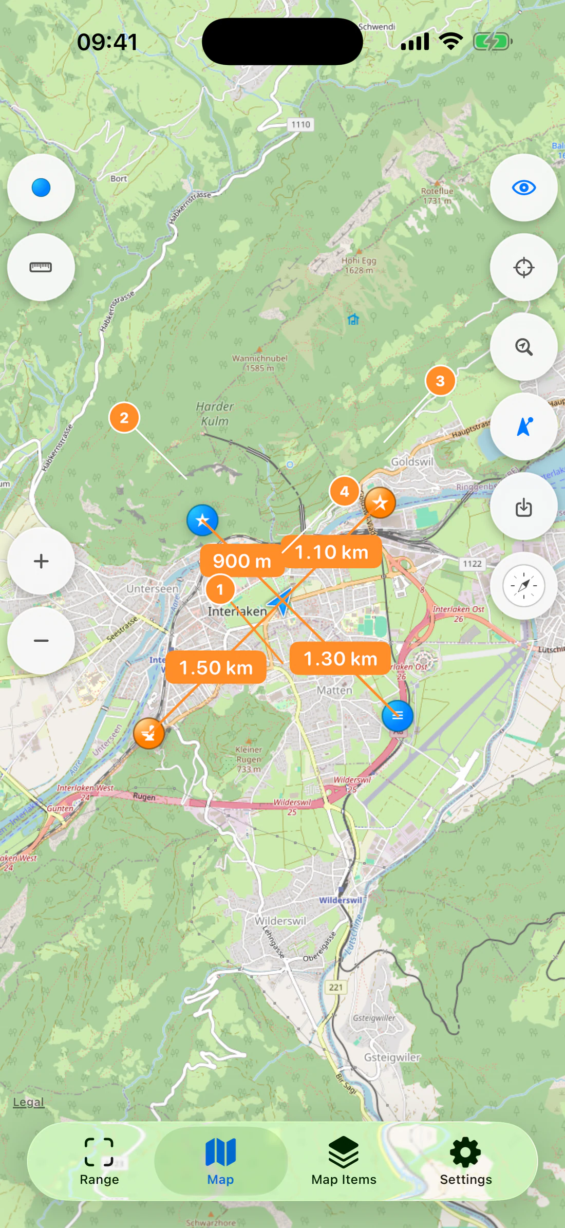
Annotated map tracking view identifying the origin, waypoint icons, lines, and distance labels.
Only checked waypoints participate. The origin is the best available current or
remembered coordinate, with map-center fallback only where the UI explicitly
uses it. Distances are geodesic. Raster and vector renderers must present the
same tracking behavior even though their projection code differs.
Transfer and privacy
GPX import/export transfers supported geographic waypoint fields. Media
attachments remain local unless explicitly exported/shared by a supported
workflow. Review exported files before sharing because names, notes, times, and
coordinates can reveal sensitive locations.
Map measurements
Map measurements store coordinate geometry independently of the selected map
renderer. Checked measurements are visible; unchecked measurements remain saved
but hidden.
Start an editor
Open Map.
Tap Measurements.
Choose a measurement kind.
Add points by tapping/long-pressing the map or adding the current map center,
according to the active editor.
Drag a handle to refine a point.
Use Undo, Redo, Clear, and color selection as needed.
Save when the geometry is valid.
Handles use an enlarged touch target and haptic feedback to make endpoint
adjustment responsive.
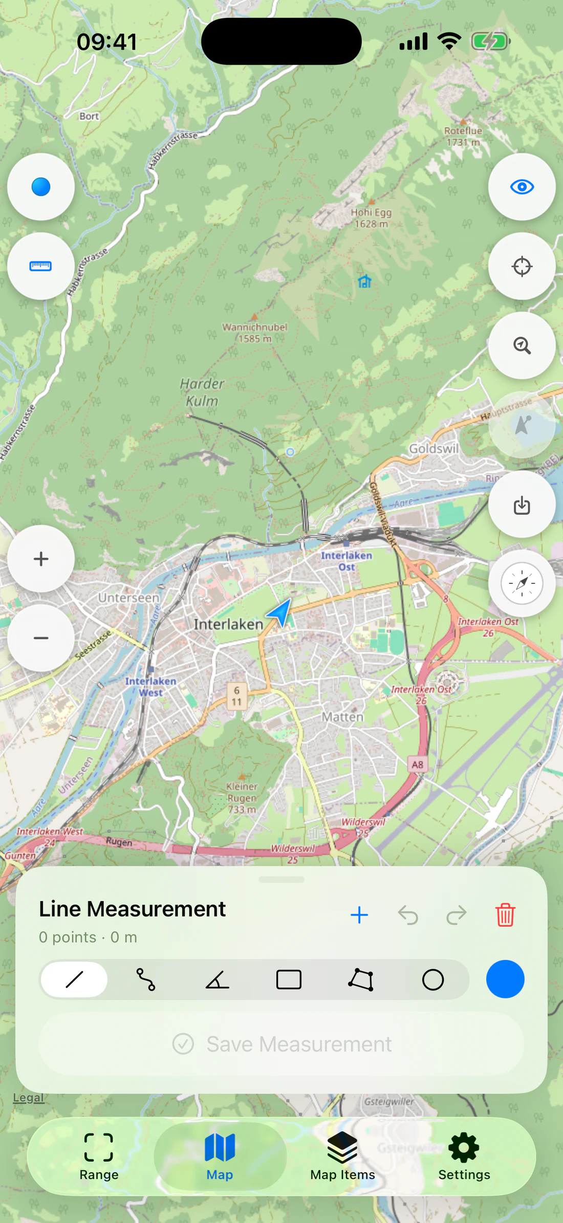
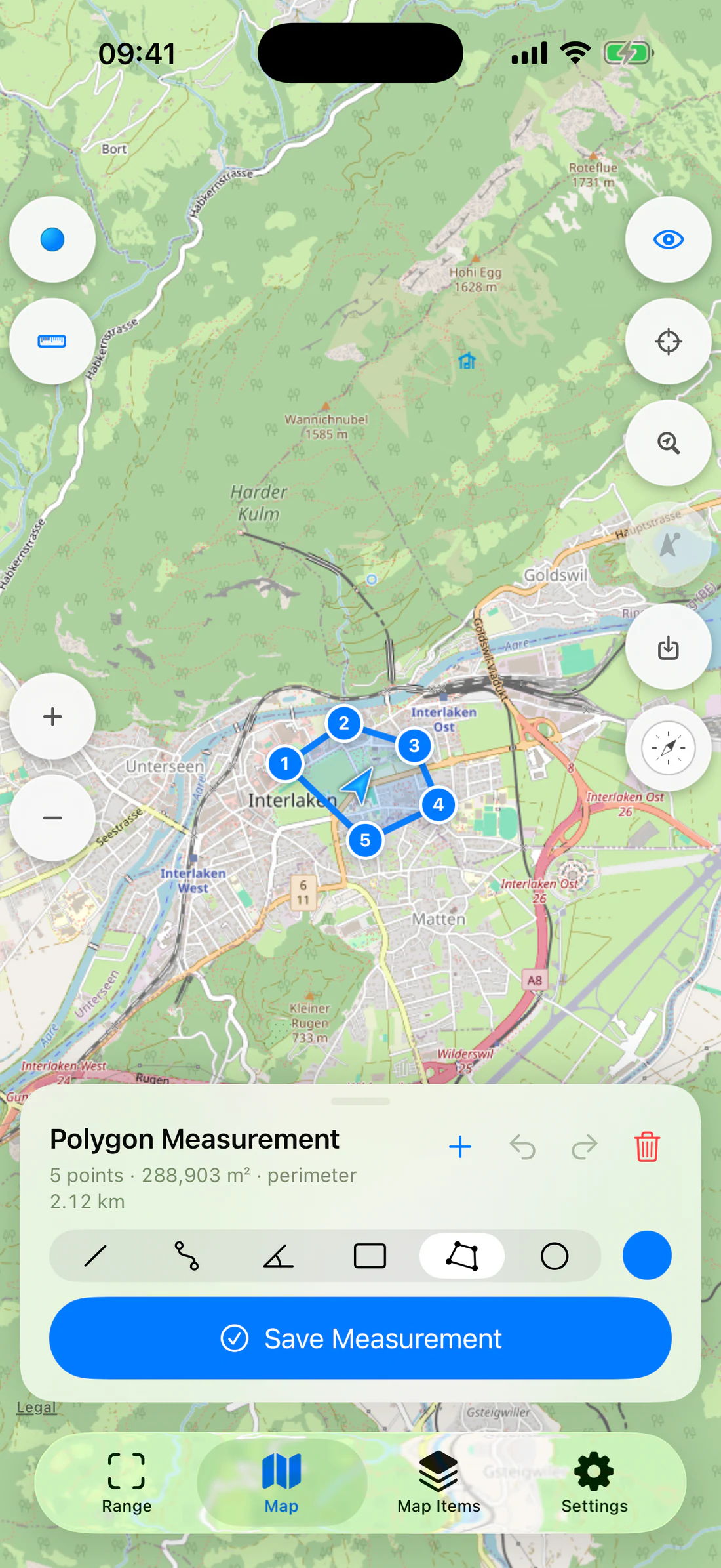
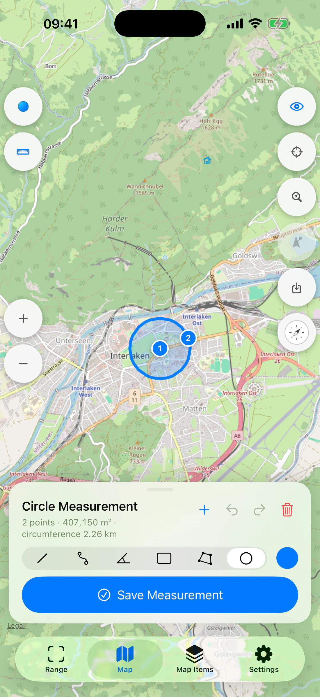
Measurement editor expanded with type selector, color, add, undo, redo, clear, save.
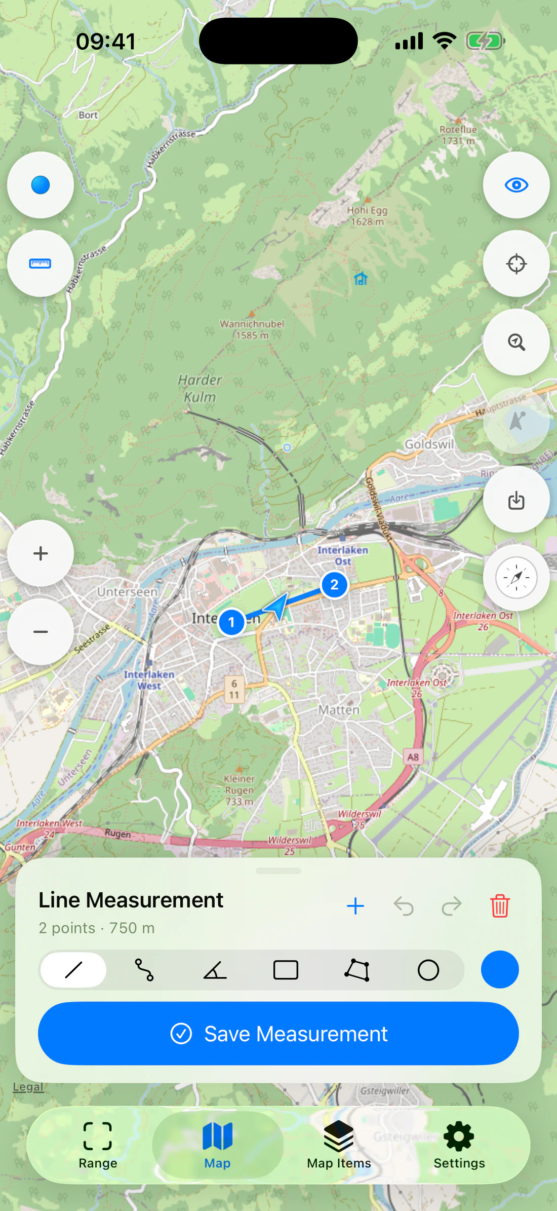
Line
A Line uses two points.
Add the trailhead.
Add the bridge.
Drag each endpoint to the intended coordinate.
Read length and initial/final bearing.
Save.
Two-point line with endpoints, length, bearing.
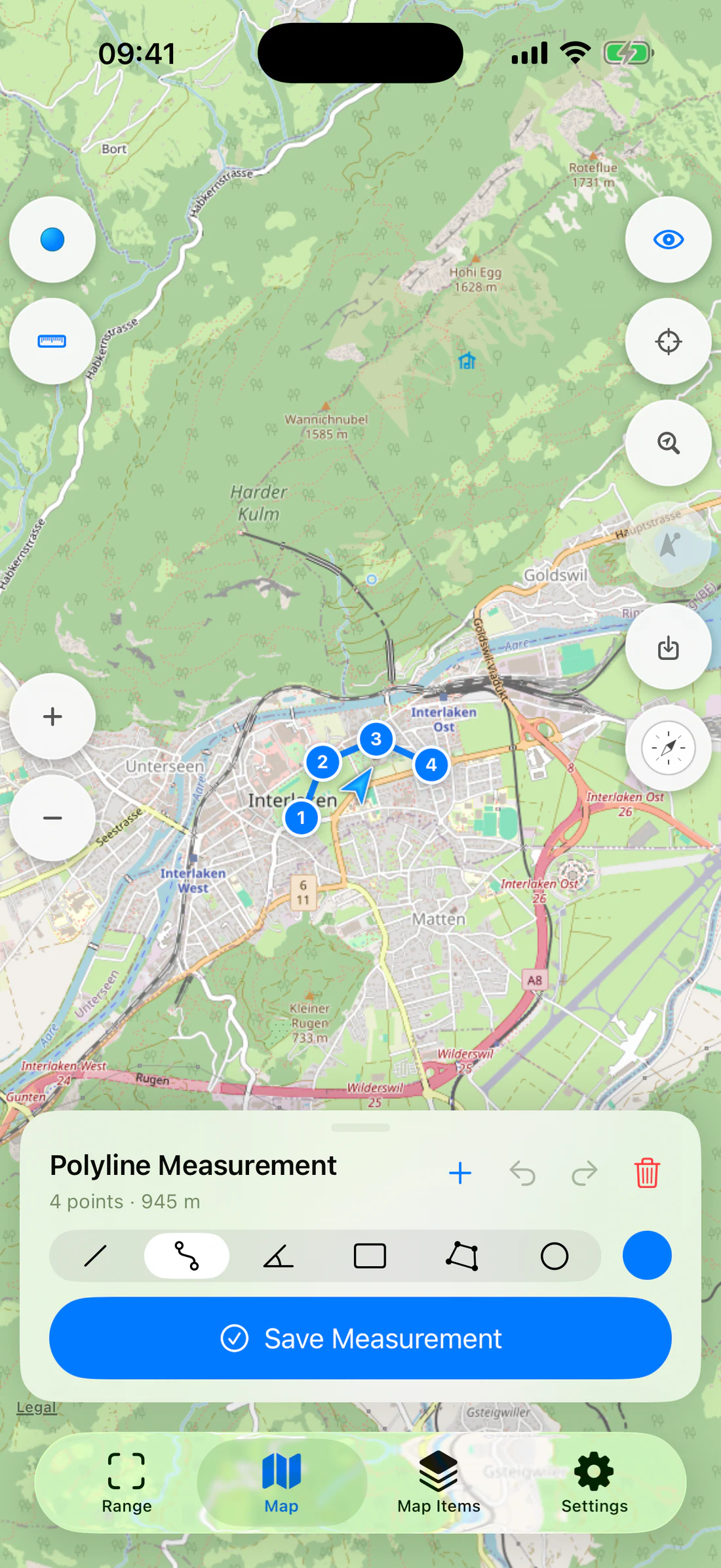
Polyline
A Polyline uses two or more connected points.
Add points along the trail in travel order.
Add enough points to represent bends without tracing insignificant map
noise.
Read total length and segment values.
Save.
Four-point path and total distance.
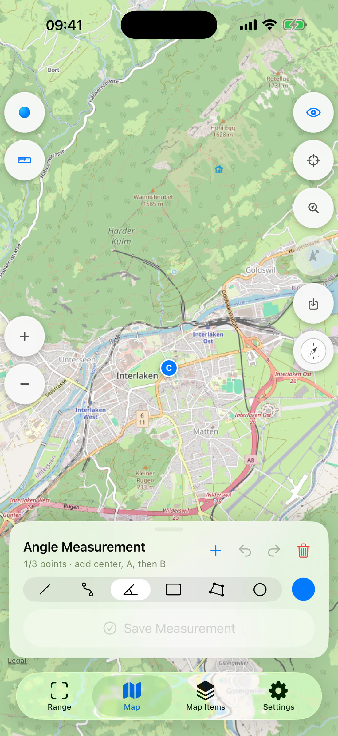
Angle: A–Center–B
The map Angle uses exactly three points in this order:
C — center/vertex;
A — first radius endpoint;
B — second radius endpoint.
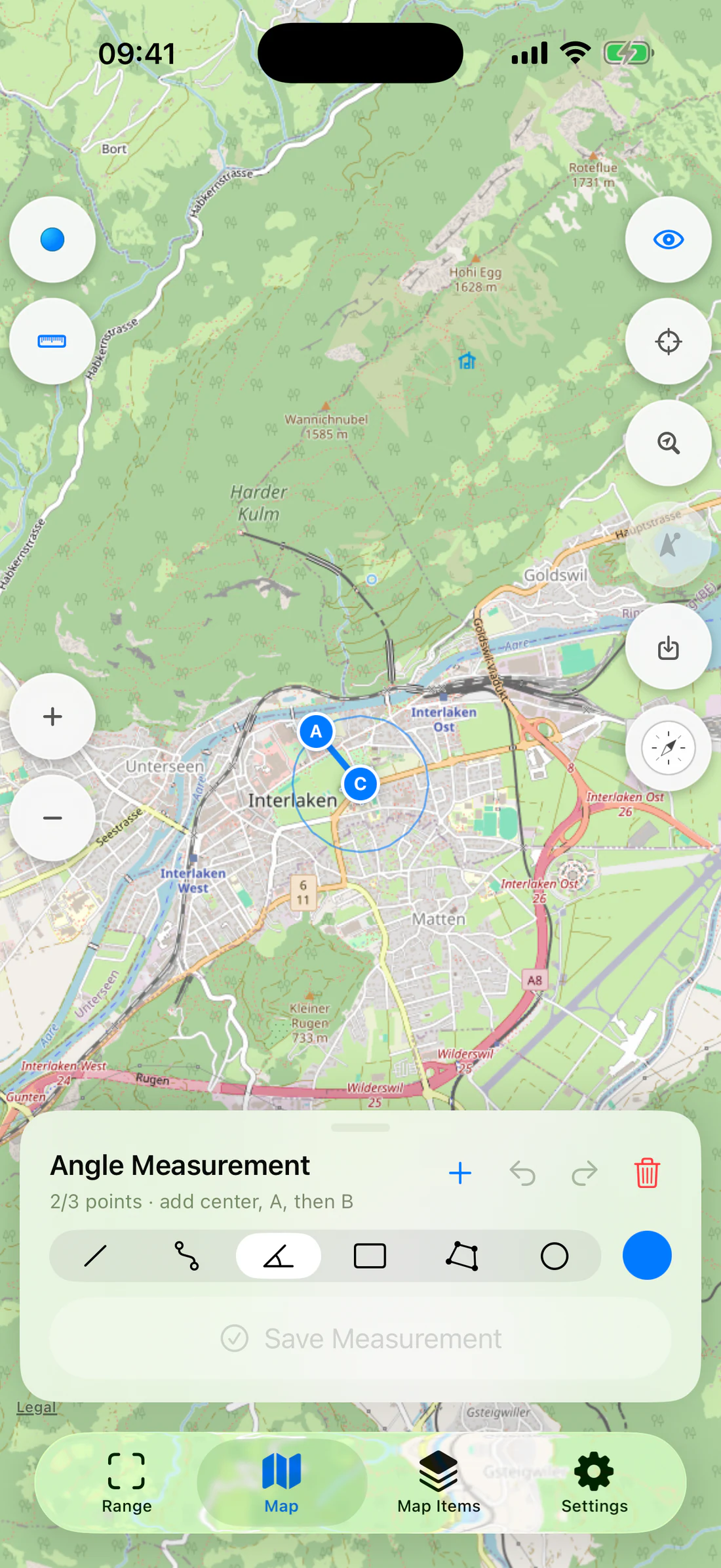
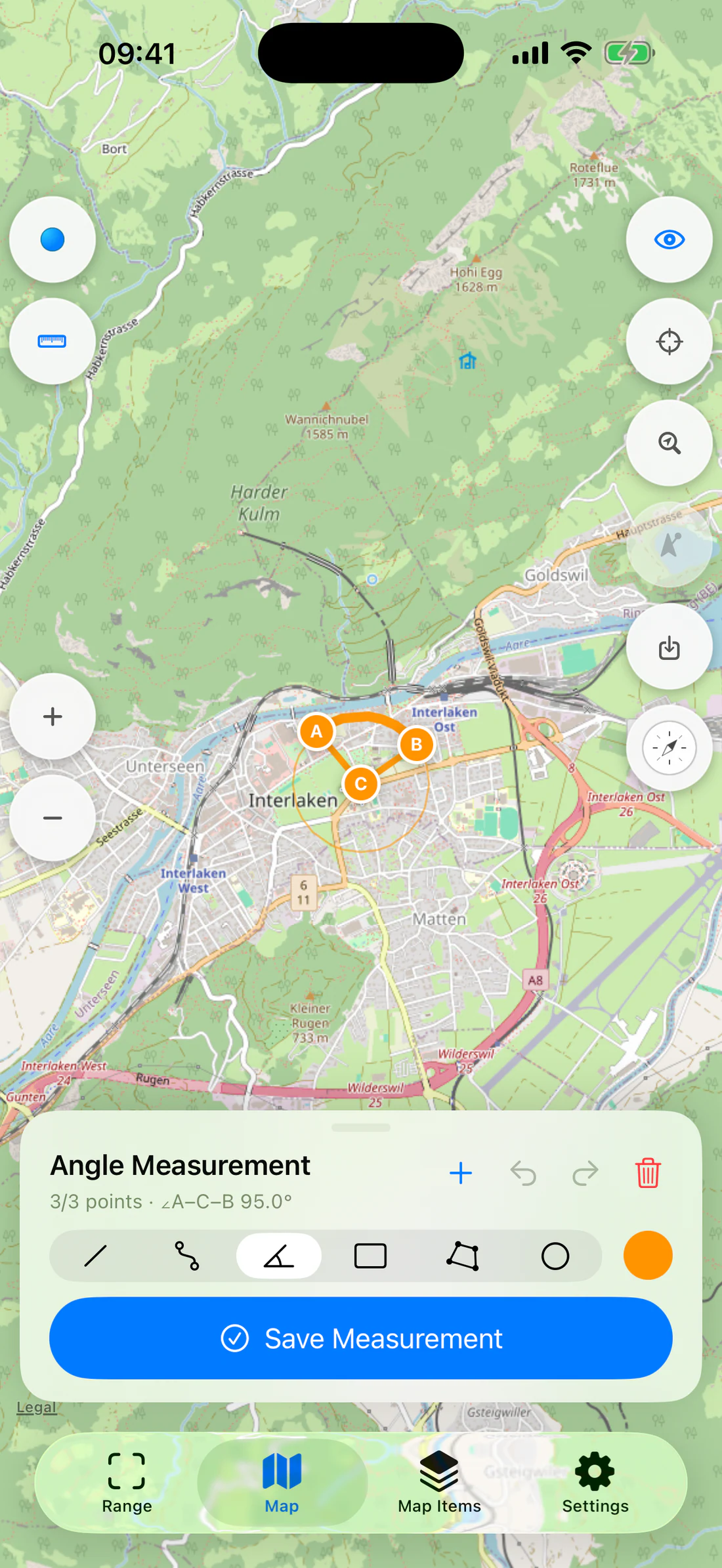
RangeFinder draws:
radius C–A;
radius C–B;
a thin reference circle whose radius updates whenever A or B changes;
a thick minor arc;
C, A, and B handles/labels.
It reports bearing to A, bearing to B, both radii, and
∠A–C–B.
Angle after adding only center C.
C and A with radius/reference circle.
C/A/B, both radii, thin circle, thick arc, angle readout.
Drag A or B and confirm the circle/arc and angle update immediately.
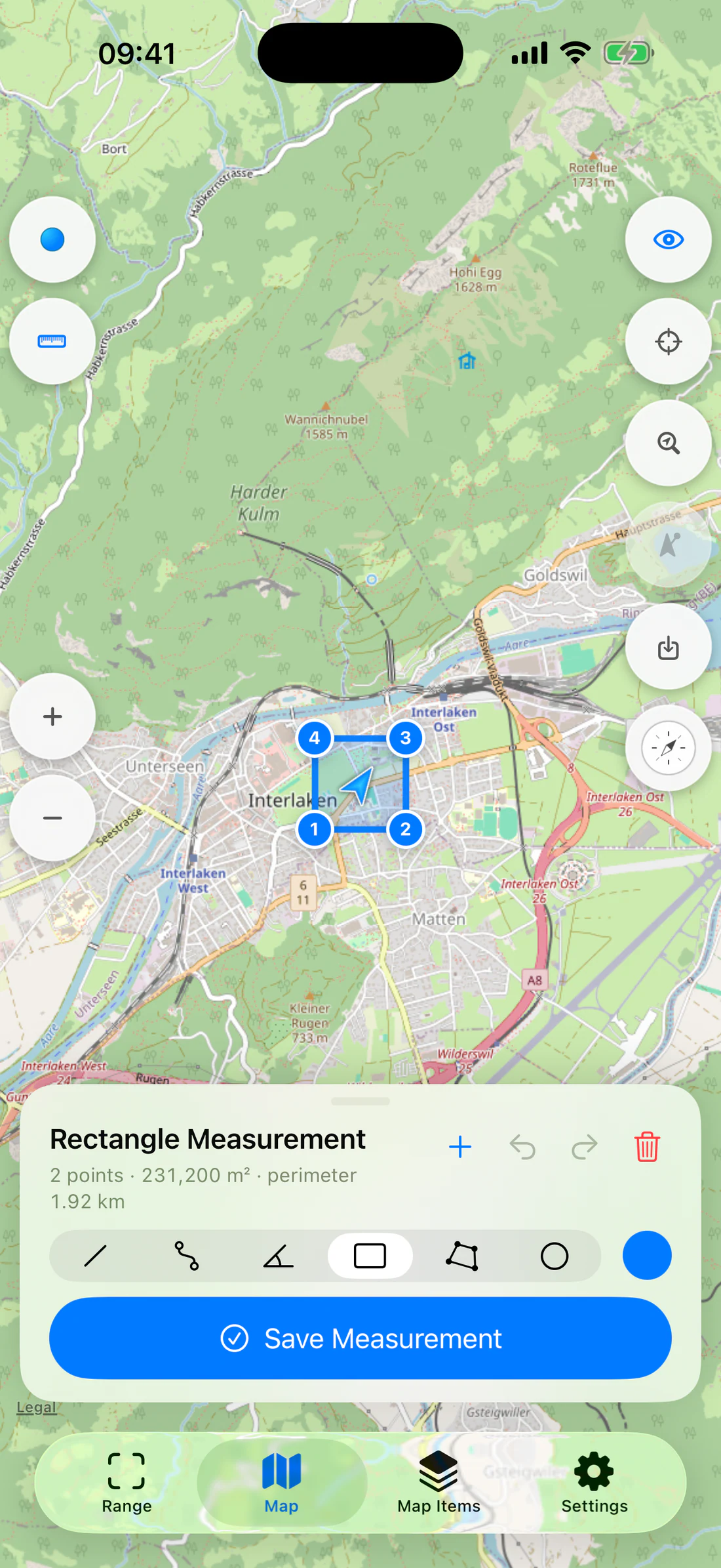
Rectangle
A Rectangle uses two opposing corners. The renderer derives the other corners.
The map draws the center-to-radius line and circumference. Read radius,
diameter, circumference, and area.
Center/radius point, circle, radius/diameter/circumference/area.
Editor controls
Control
Action
Add at Center
Adds the current map-center coordinate
Undo
Removes/reverts the latest editor change
Redo
Reapplies an undone change
Clear
Removes draft points after confirmation where required
Color
Shows real color circles and selects geometry color
Save
Persists only valid geometry
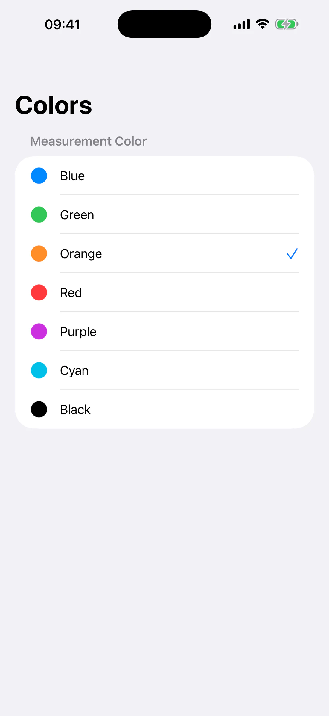
Color list with actual colored circles.
The renderer must not create an empty multipoint/polyline. A line is drawn only
after the geometry has the minimum required vertices.
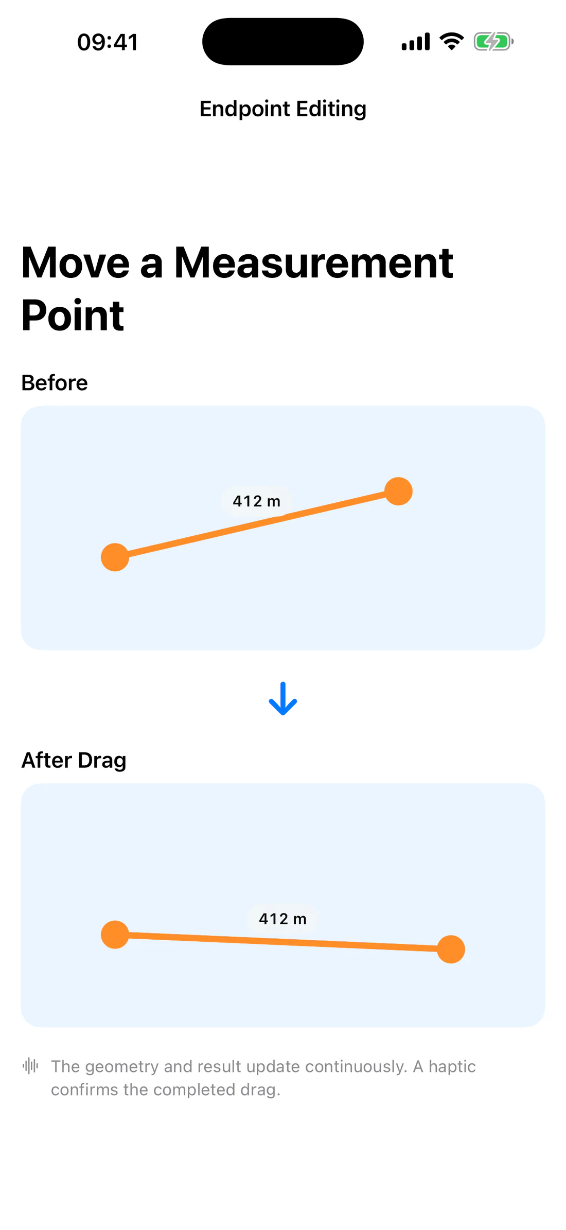
When you drag an endpoint, the geometry and result update continuously. A
haptic confirms the completed drag.
Drag an endpoint; static before/after pair, caption notes haptic feedback.
Manage saved measurements
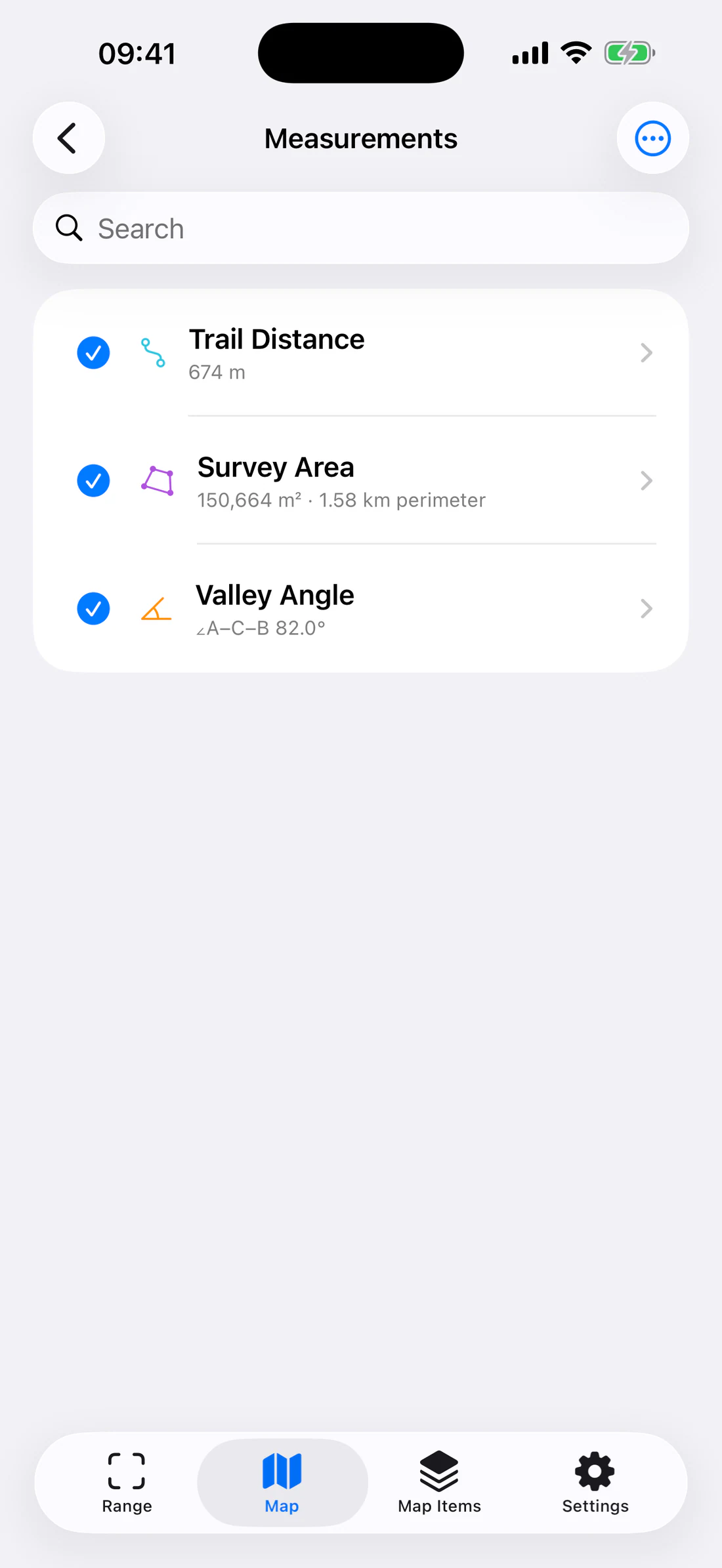
Open Map Items → Measurements.
Tap the checkmark/circle to show or hide an item.
Search the list.
Open detail readouts.
Rename or edit note/color where exposed.
Delete with confirmation.
Use Transfer for import/export.
Measurement list with checked/unchecked items.
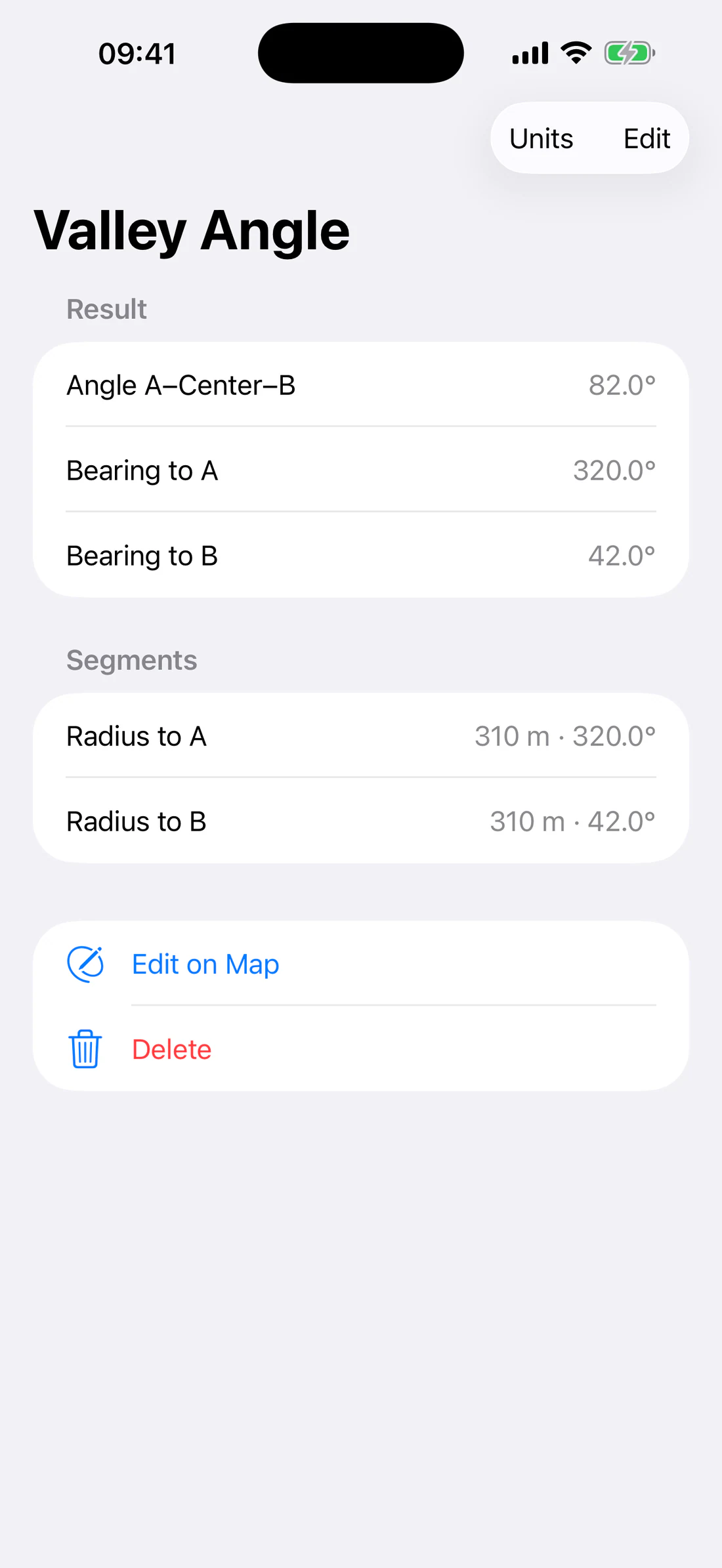
Detail readouts vary by kind and can include:
total distance;
segment distances;
initial/final bearing;
area/perimeter;
radius/diameter/circumference;
A/B bearings and radii;
A–Center–B angle.
Angle detail with A/B bearings, radii, and angle result.
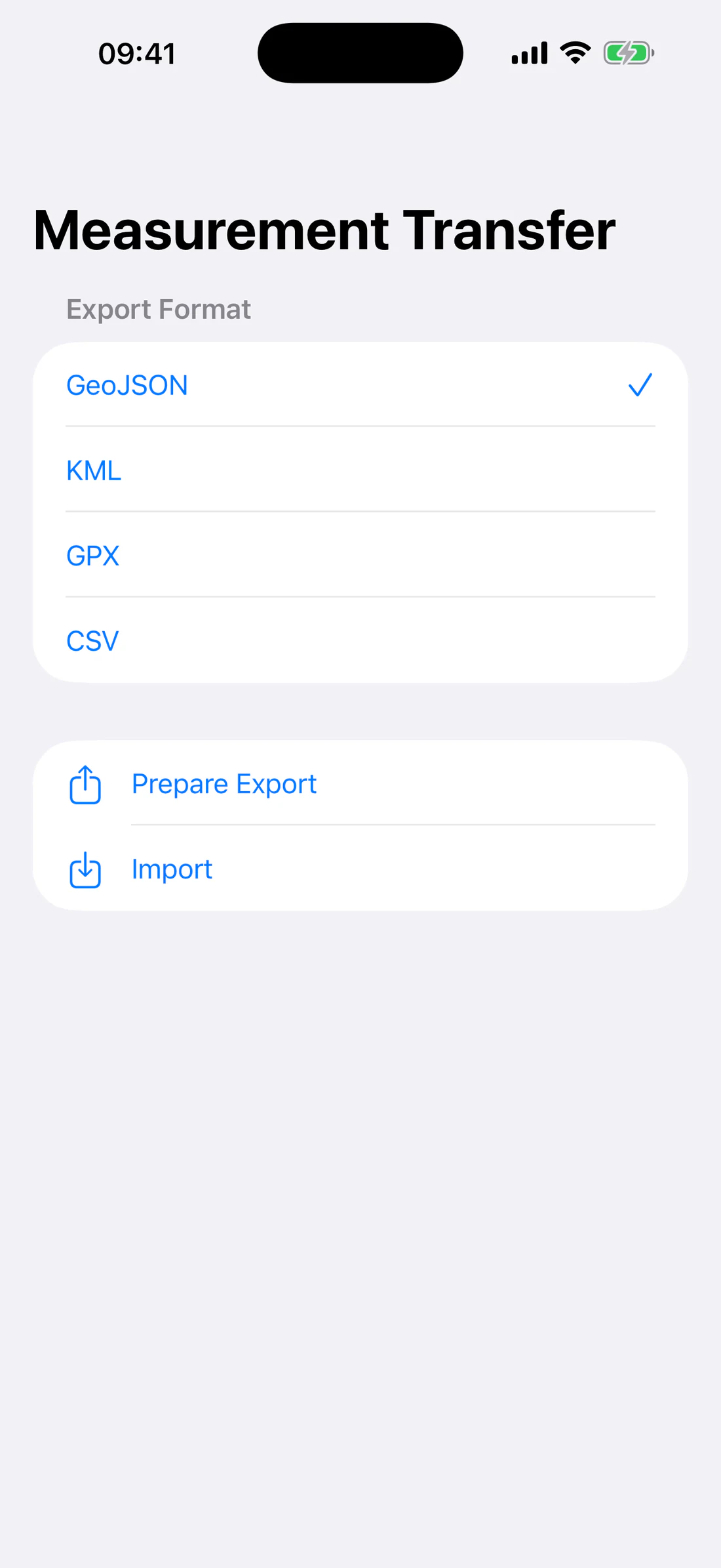
Transfer formats
Format
Typical use
GeoJSON
General GIS geometry and properties
KML
Earth/map applications
GPX
Route/track/point exchange
CSV
Tabular inspection and spreadsheet workflows
Export format selector for GeoJSON/KML/GPX/CSV.
Imports may be partial when a source contains unsupported geometry or invalid
records. Review the import summary rather than assuming every item was accepted.
Exports use the selected unit/coordinate presentation where applicable but
retain the geometry needed by the target format.
Accuracy and limitations
Results follow the coordinates placed on the map, not camera depth.
Map imagery may be offset from surveyed ground truth.
Area and distance calculations cannot correct a wrongly placed point.
Use sufficient vertices for a curved route or irregular boundary.
Avoid claiming cadastral/survey accuracy without authoritative data.
Repeat with a different map source when imagery alignment is uncertain.
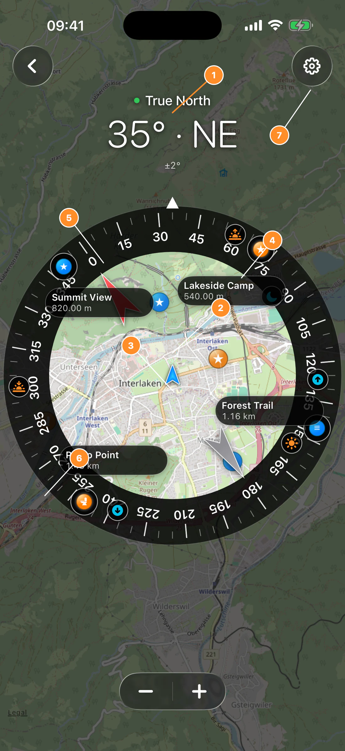
Map Compass
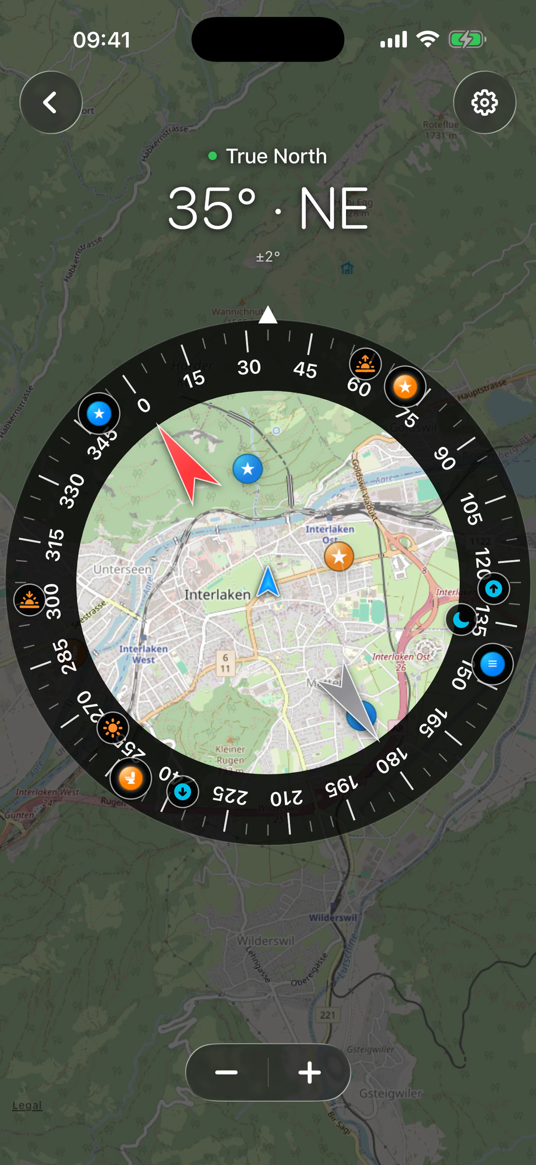
Map Compass places a rotating vector compass dial over the selected map and
combines heading, selected waypoints, current/remembered location quality, and
optional astronomy markers.
Open Map Compass
Tap the compass button on Map. The workspace contains:
rotating dial and cardinal marks;
north/south needle;
heading and north-reference readout;
selected waypoint icons around the dial;
optional waypoint name/distance callouts;
optional Sun, Moon, sunrise, sunset, moonrise, and moonset markers;
The dial and its waypoint/astronomy markers rotate continuously with heading.
Its labels use a smaller system font to remain readable without dominating the
map.
Select waypoints
Waypoint selection has two stages:
Open Map Items → Waypoints and check each waypoint that may appear.
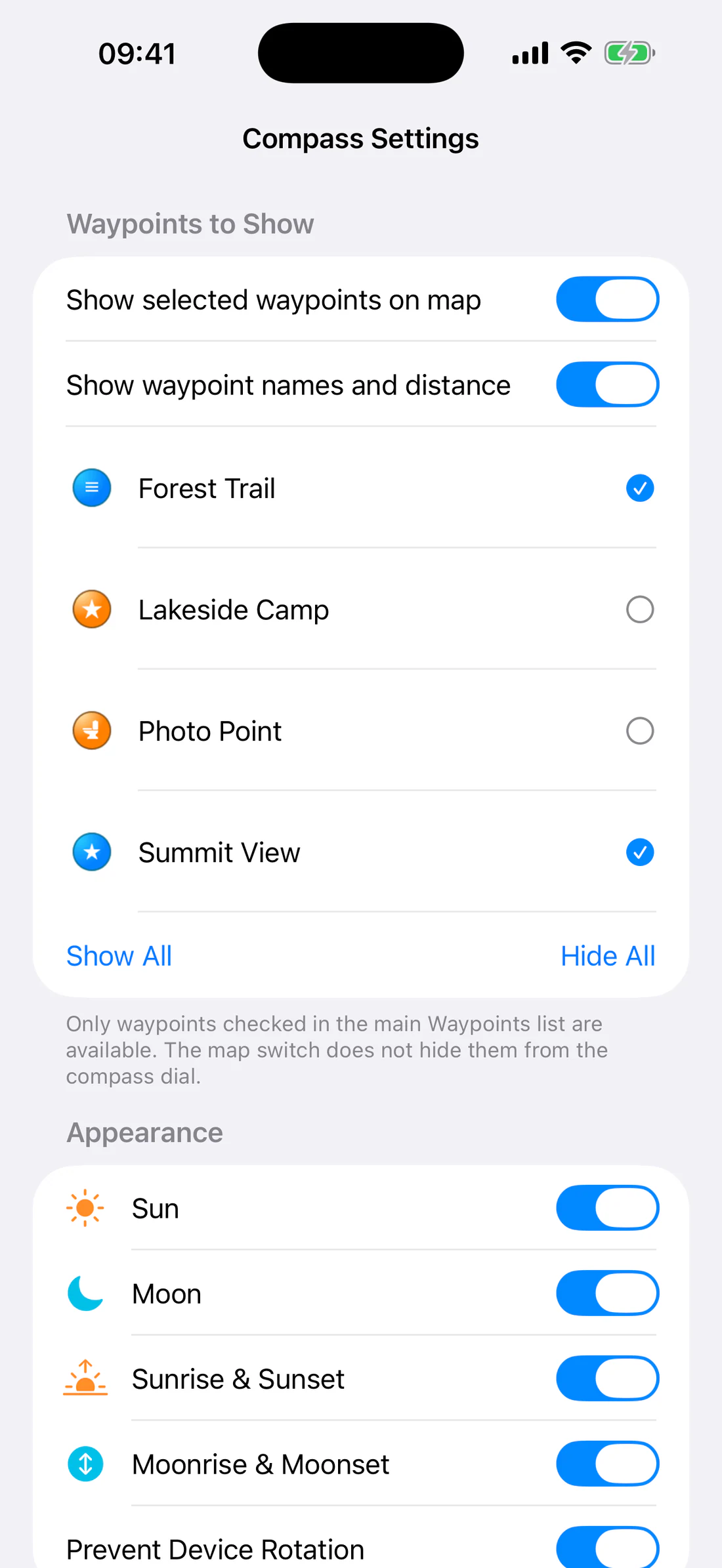
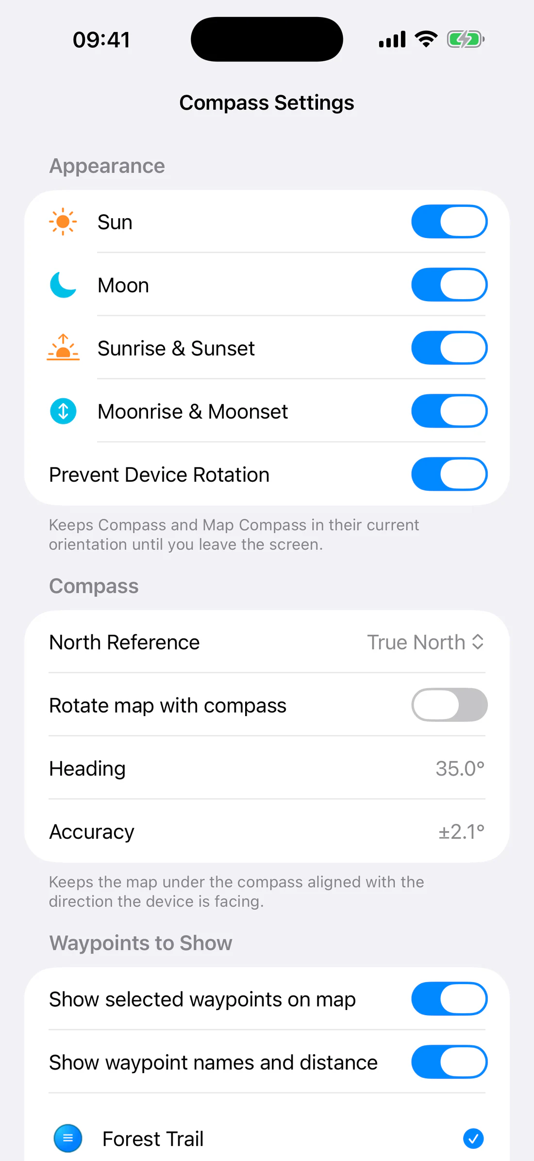
Open Map Compass → Settings → Waypoints to Show and include/exclude each
available waypoint.
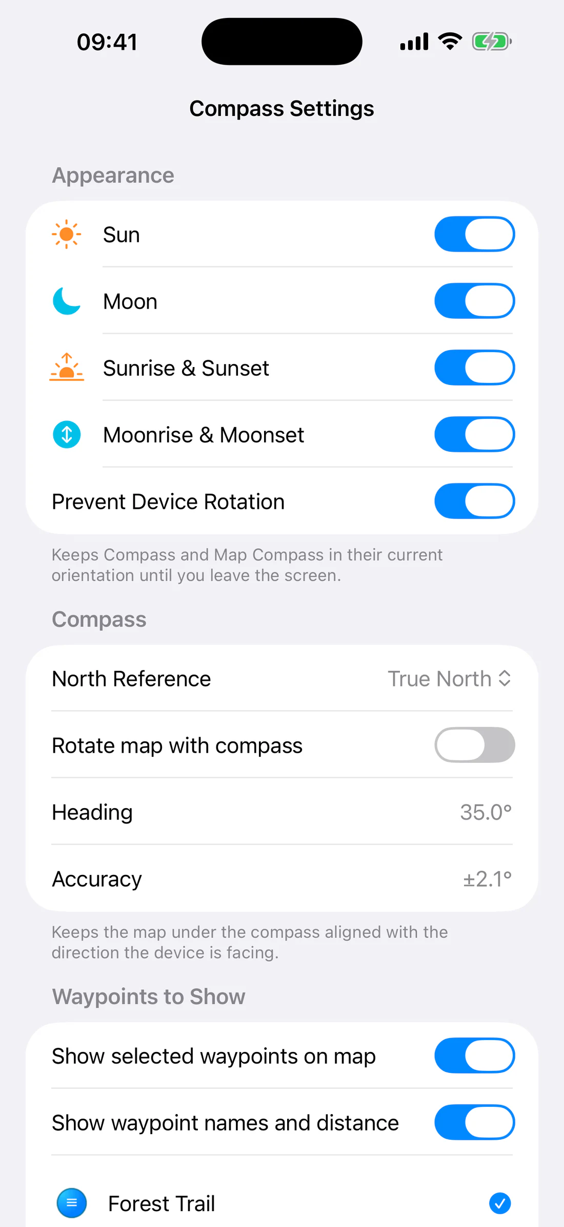
Compass Settings list with mixed selected/unselected waypoints and icons.
Use Show All or Hide All for the currently available checked waypoints.
An unchecked main-list waypoint is not offered to Compass Settings.
Selected dial waypoints are not limited to the visible map viewport. They
remain arranged by bearing around the dial.
Show names and distances
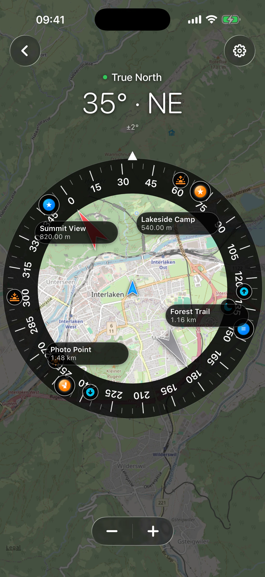
Enable Show waypoint names and distance. Each selected dial icon receives a
callout with its waypoint name and geodesic distance from the current or
remembered origin.
Disable the switch for a cleaner dial while retaining the selected icons.
Names/distance off while waypoint icons remain.
Show waypoints on the map
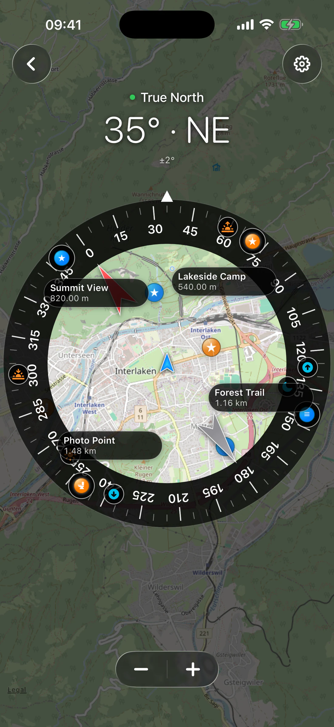
Show selected waypoints on map controls only the underlying map layer.
On: selected waypoints appear on both dial and map.
Off: selected waypoints remain on the dial but are hidden from the map.
Show selected waypoints on map off; waypoints remain on dial only.
Same state with map switch on.
Rotate the map with heading
Enable Rotate map with compass to continuously align the underlying map
with device heading. The update changes bearing without changing map zoom.
Disable it to reset the map to north-up. The dial still rotates with heading.
Choose true or magnetic north
Tap the heading/reference readout or use Compass Settings:
True North uses location-dependent correction when available.
Magnetic North reports magnetic heading.
If true north cannot be produced, the UI states that magnetic north is being
used. Heading accuracy is shown as ±…° when available.
These are directional planning markers calculated for the current location and
time. They are not safety-navigation instructions.
Zoom
Use the dedicated plus/minus buttons to change the map background scale. Zoom
does not change waypoint bearing or the compass dial’s angular layout.
Coordinate quality
The central location icon indicates the origin. A red dot means the app is
using remembered last-good location rather than a fresh valid coordinate.
Waypoint distance and astronomy direction inherit that limitation.
Calibrate horizon and inclination
Open Compass Settings → Sensors:
Place the device against a known level/reference orientation.
Wait for motion data.
Tap Calibrate Horizon and Inclination.
Verify the displayed zero.
Use Reset Calibration to remove the offset. Use Restart Sensors to
reconnect motion, heading, and location updates without discarding calibration.
Calibration changes the displayed zero; it does not physically recalibrate the
sensor hardware or correct magnetic interference.
Prevent device rotation
Prevent Device Rotation is on by default and keeps Compass/Map Compass in
their current interface orientation until you leave the screen. Heading and
map rotation continue to respond to sensor changes.
Troubleshooting
Waypoint is missing
check it in the main Waypoints list;
include it in Compass Settings;
obtain a current or remembered coordinate;
confirm the waypoint has valid coordinates.
Map rotates but changes scale
Continuous heading updates must change only map bearing. Record a reproducible
screen/video if zoom changes without using pinch or plus/minus.
Heading is wrong
Move away from magnetic interference, remove magnetic accessories, switch
north reference deliberately, restart sensors, and compare with a known
direction.
Astronomy
Astronomy calculates Sun, Moon, planetary positions, and light/twilight events
for the current or remembered coordinate. It remains available while Weather
is hidden in this release.
Astronomy and map directions support planning and photography. They are not
navigation or life-safety predictions.
Open Astronomy
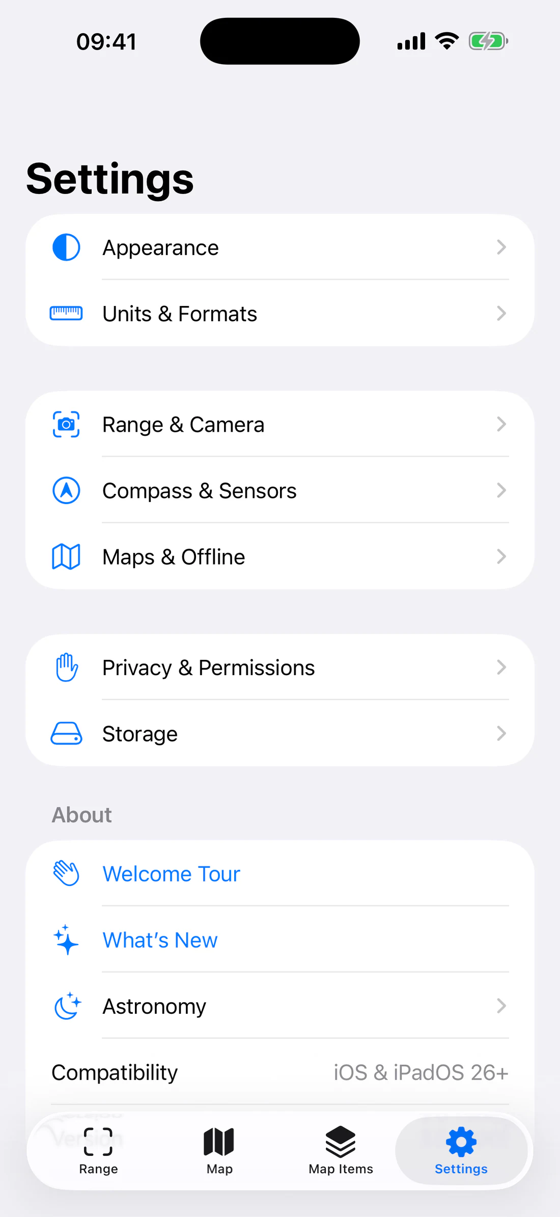
Open Settings → Astronomy. The screen uses the current/remembered location,
altitude when available, selected date/time context, and on-device astronomy
calculations.
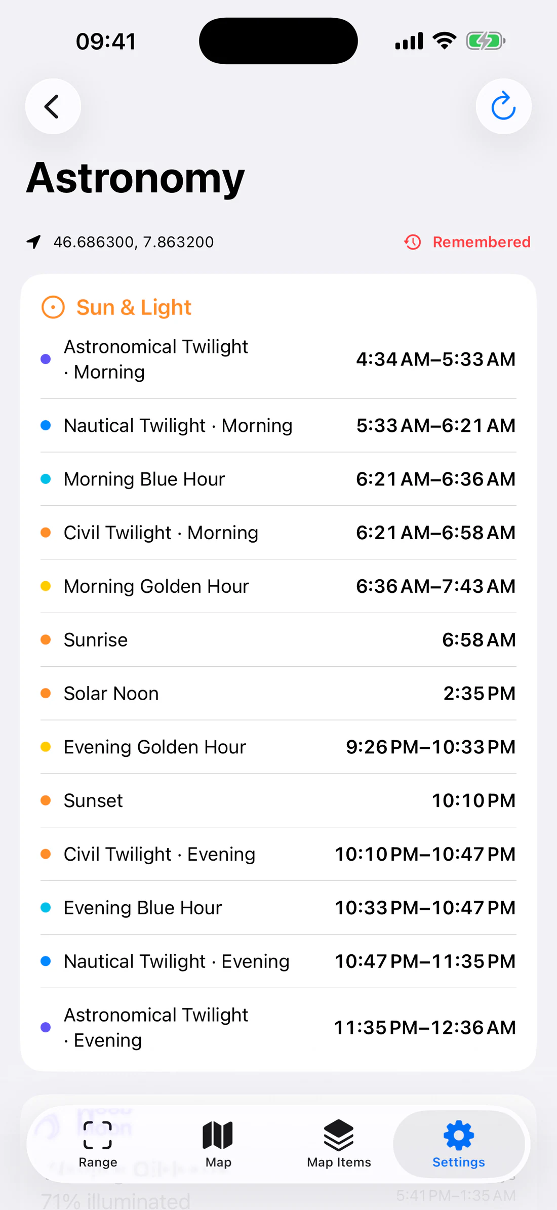
Astronomy using remembered coordinate with visible quality label.
A warning indicates when the coordinate is remembered or otherwise lower
quality.
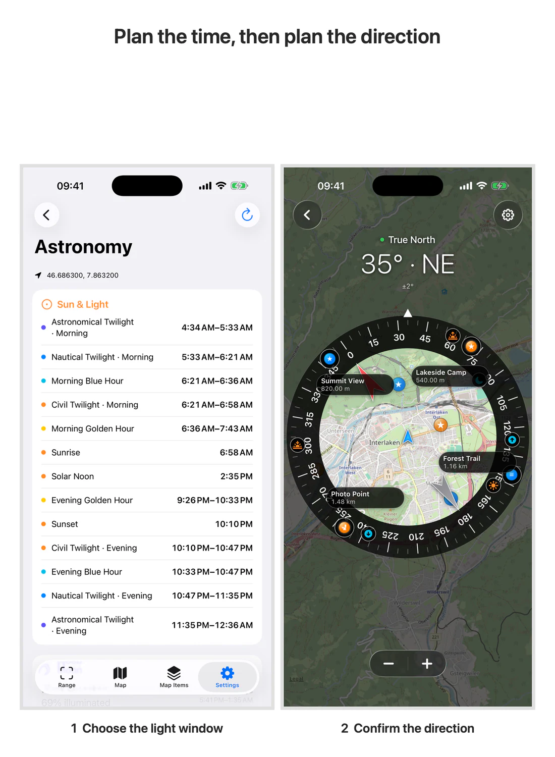
Sun and light events
Events are displayed by their calculated start time. The complete event set is:
Astronomical Twilight · Morning.
Nautical Twilight · Morning.
Civil Twilight · Morning.
Morning Blue Hour.
Morning Golden Hour.
Sunrise.
Solar Noon.
Evening Golden Hour.
Sunset.
Civil Twilight · Evening.
Evening Blue Hour.
Nautical Twilight · Evening.
Astronomical Twilight · Evening.
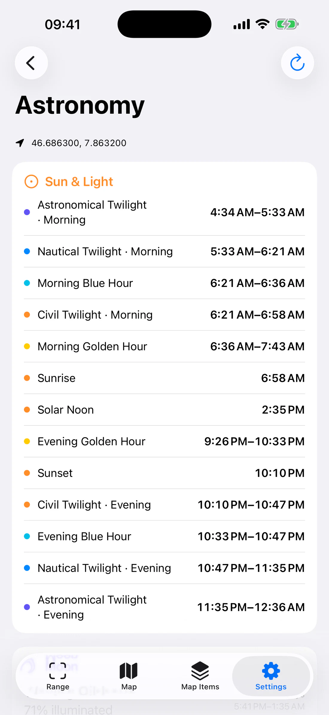
Complete chronological Sun & Light card.
Blue/golden hours overlap civil-light intervals, so their relative row order
can vary when two intervals begin at the same or nearly the same time. Read the
times rather than assuming a fixed semantic order.
An interval shows start–end; a single event such as sunrise shows one time. A
dash means the event cannot be produced for the current date/location state.
Moon
The Moon card shows:
phase name and matching planetary-symbol asset;
illuminated percentage;
age in days;
moonrise and moonset interval when available.
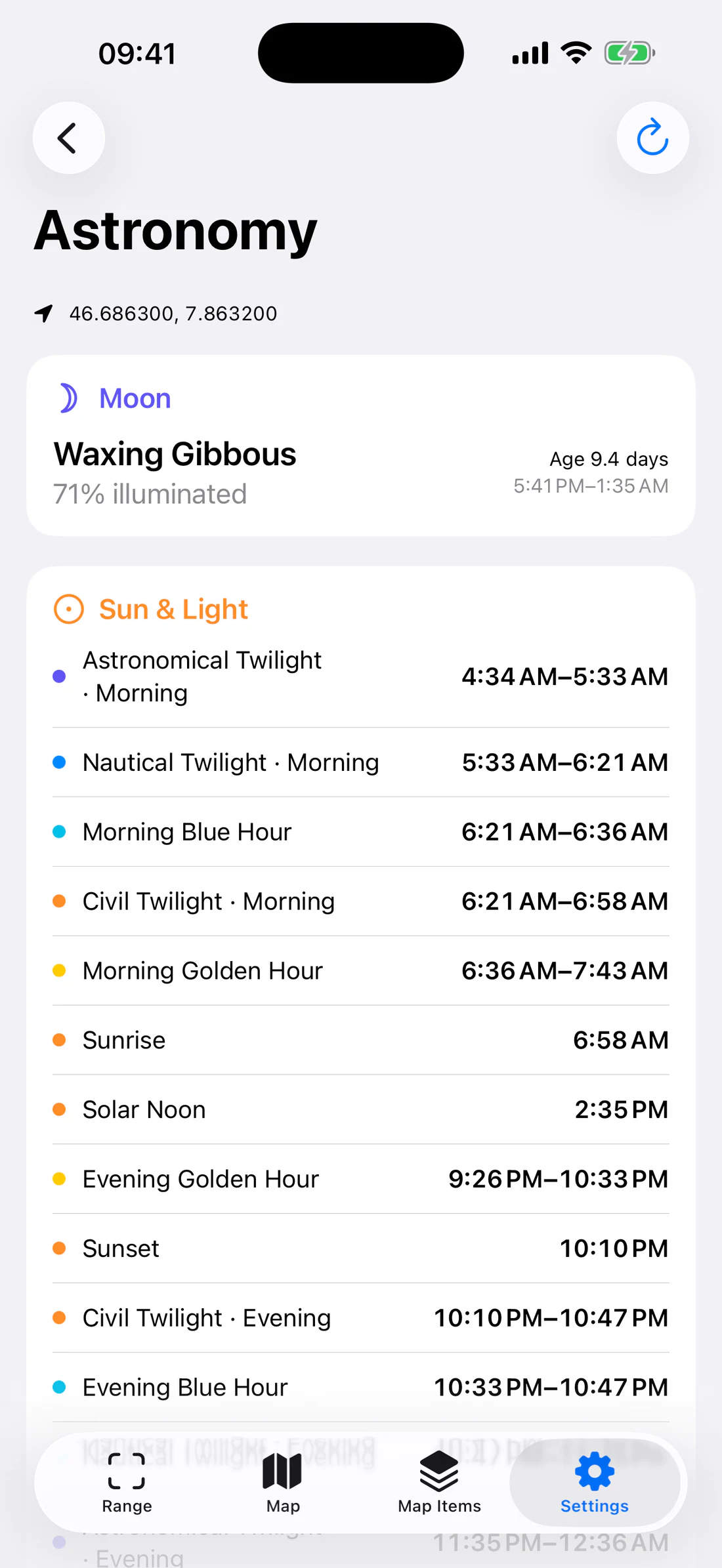
Moon phase symbol, illumination, age, rise/set.
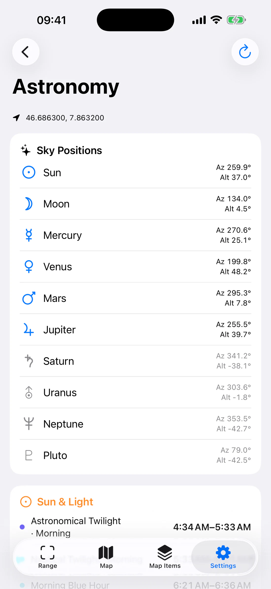
Sky positions
The Sky Positions list includes:
Sun;
Moon;
Mercury;
Venus;
Mars;
Jupiter;
Saturn;
Uranus;
Neptune;
Pluto.
Each row shows azimuth and apparent altitude. Imported planetary symbols adapt
to the current light/dark color scheme. A body below the horizon is presented
with secondary emphasis.
Sky Positions with all planetary symbols and azimuth/altitude.
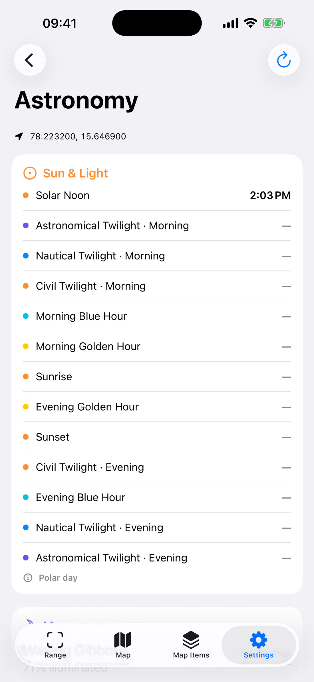
Polar and missing-event states
At high latitudes, the Sun may not rise or set on a selected date. Astronomy
identifies non-normal solar states such as polar day, polar night, or a
transition instead of manufacturing missing times.
Polar-day or polar-night explanatory state.
Photography planning example
Set or visit the planned viewpoint so RangeFinder has its coordinate.
Open Astronomy.
Find the desired morning/evening golden or blue hour.
Note sunrise/sunset time.
Open Map → Map Compass.
In Compass Settings, enable Sun and Sunrise & Sunset.
Compare the marker direction with selected photo waypoints.
Arrive early enough to account for terrain, buildings, and weather.
Two-panel Astronomy golden-hour time and Map Compass Sun direction.
Astronomical horizon calculations do not know that a mountain or building
blocks the local horizon. Use terrain/site knowledge.
Refresh and recovery
Astronomy refreshes when its requested coordinate/date context changes and can
periodically refresh while Map Compass remains open.
If Astronomy is unavailable:
wait for current or remembered location;
verify Location permission;
restart sensor/location services;
try a valid non-polar date/location;
reopen the screen;
report the coordinate quality, date, device, and app version if the problem
persists.
Weather API availability does not control Astronomy in this release.
Settings reference
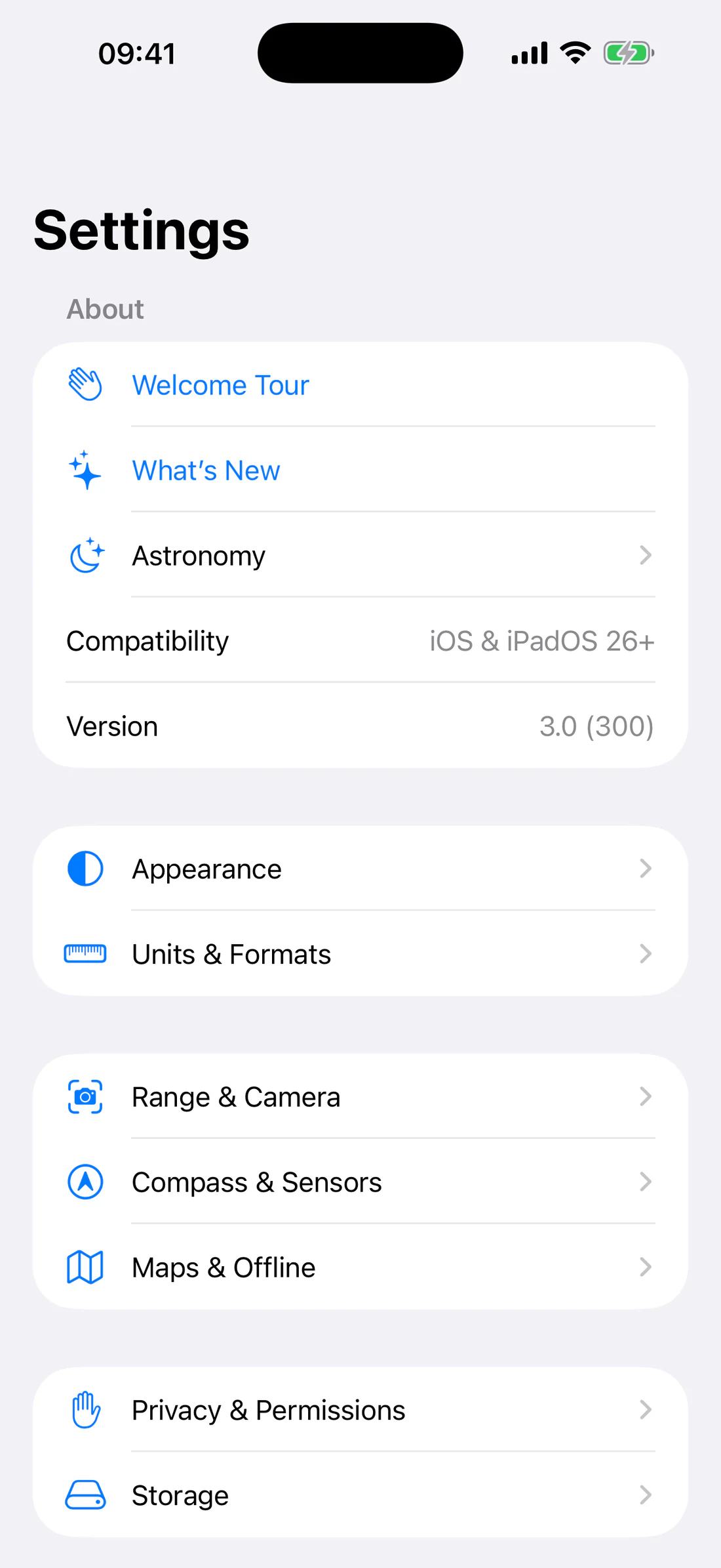
The main Settings screen groups preferences in a stable order so related
instrument settings are easier to find.
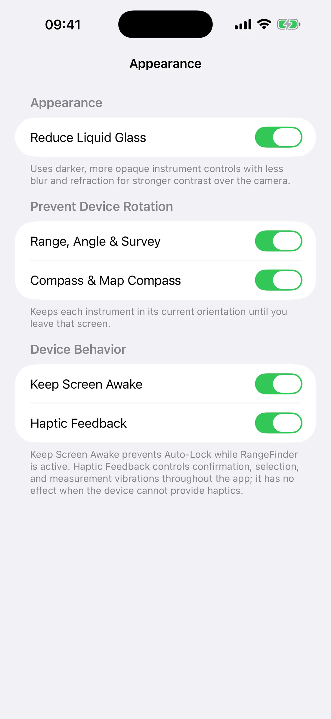
On by default. Uses darker, more opaque camera-instrument controls with less
blur/refraction for stronger contrast. Range-screen button text and icons
remain white.
Prevent Device Rotation
Separate switches, both on by default:
Range, Angle & Survey;
Compass & Map Compass.
Each keeps the current interface orientation until the screen is left. Sensor
angles and compass heading still update.
Device behavior
Keep Screen Awake prevents Auto-Lock while RangeFinder is active.
Haptic Feedback controls confirmation, selection, and measurement
vibrations; it has no effect on unsupported hardware.
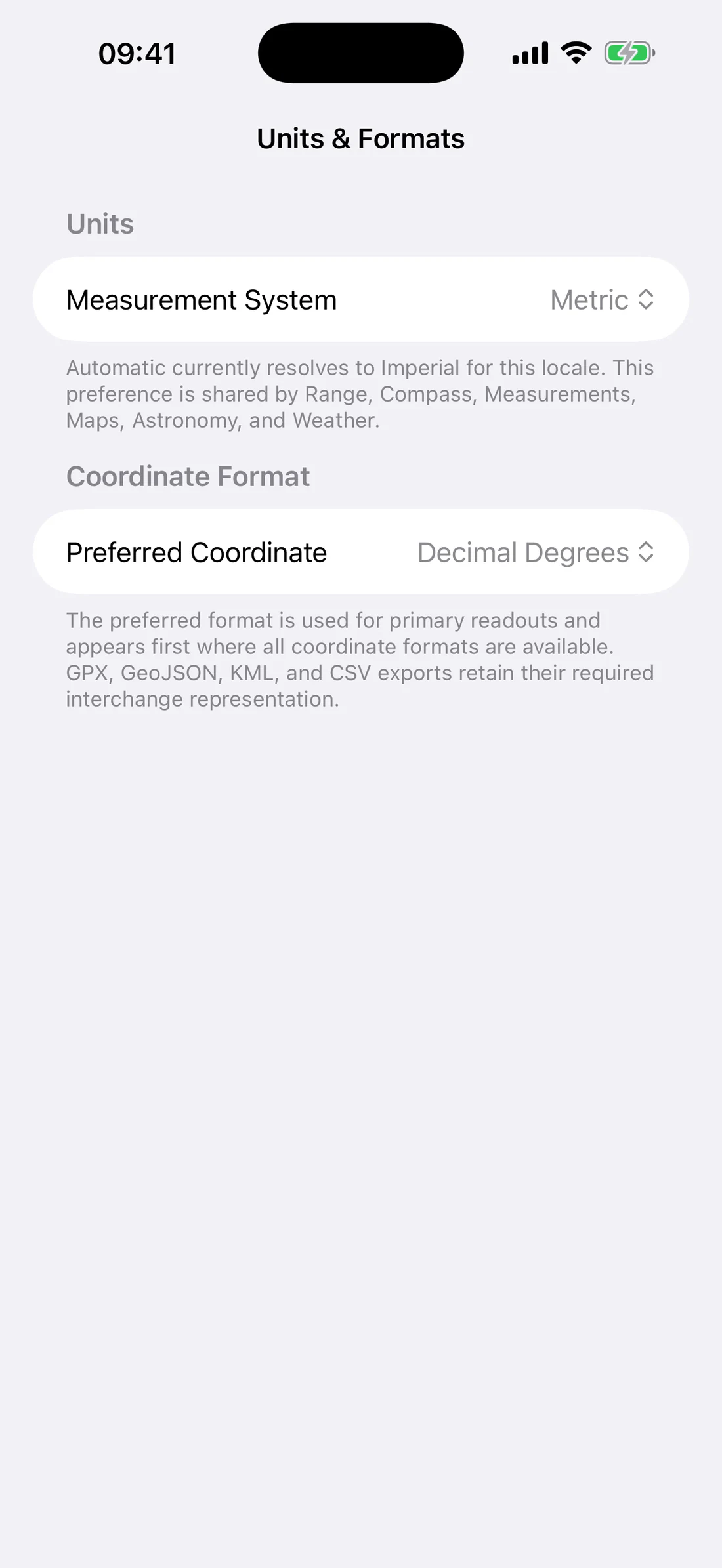
Units & Formats
Automatic/Metric/Imperial and coordinate format.
Measurement System
Automatic;
Metric;
Imperial.
Automatic resolves from the current locale. The preference is shared by Range,
Compass, Measurements, Maps, Astronomy, and formatters used by hidden Weather
implementation.
Preferred Coordinate
Choose the primary coordinate representation. It appears first where all
representations are available. GPX, GeoJSON, KML, and CSV retain the
interchange representation their format requires.
Range & Camera
Photo composition, outline, Reticle Library.
Saved Photo Content — Camera + Reticle, Camera + Reticle + Measurement,
or Whole Screen.
Camera and LiDAR device choices remain inside each instrument because formats,
zoom limits, depth support, and active capture sessions are instrument-specific.
Compass & Sensors
Compass & Sensors sections.
Appearance
Sun;
Moon;
Sunrise & Sunset;
Moonrise & Moonset;
Prevent Device Rotation.
Compass
North Reference;
Rotate map with compass;
live Heading;
Accuracy.
Waypoints to Show
Show selected waypoints on map;
Show waypoint names and distance;
per-waypoint selection;
Show All/Hide All.
Only waypoints checked in the main Waypoints list are available.
Sensors
live Horizon and Inclination;
Calibrate Horizon and Inclination;
Reset Calibration;
Restart Sensors.
Maps & Offline
Map Sources and Offline links.
Map Sources opens the categorized renderer/source list.
Offline opens the thumbnail-based Offline Areas workspace.
Privacy & Permissions
Mixed permission states plus Open System Settings and data-handling text.
Shows current authorization state for:
Location;
Camera;
Photos.
Use Open System Settings to change denied/restricted access. Microphone
access is requested in the waypoint voice workflow and is covered by the local
data summary.
Storage
Offline quota/bonus and transient cache section.
Offline maps
Shows current storage limit and bonus state:
initial 512 MiB;
first completed map adds 512 MiB and increases the per-area limit to 16,000
tiles.
Transient network cache
Shows temporary network-cache size. Clear Transient Network Cache removes
temporary responses but does not delete offline map areas, waypoints,
measurements, photos, voice messages, or saved captures.
What’s New opens release information without a redundant Continue button.
Astronomy.
Compatibility.
Version/build display.
Premium and Weather controls remain hidden in this release.
Support
Support email and website.
Support is the final Settings group:
email: support2026@lifewaresolutions.com;
RangeFinder website.
Include app version, iOS/iPadOS version, device, selected instrument/source, and
exact error text. Do not send keys or private media/location unless deliberately
needed.
Instrument-local settings
Range, Angle, and Angle Survey use a common order where applicable:
Appearance.
Compass/horizon calibration.
Sensors.
LiDAR.
Cameras.
Ranging/measurement controls.
Reticle.
Lens filter.
Photo.
Unavailable sections should collapse rather than leave large blank spaces
under headings such as Camera Calibrated or Back LiDAR Camera.
Accuracy, field technique, privacy, and storage
Direct, calculated, and geographic results
Result
Basis
LiDAR
Direct depth samples in the target
Surface
AR raycast to detected geometry
Known Size
Camera rays/intrinsics plus known physical input
Waypoint distance
Geodesic coordinate distance
Map measurement
User-placed coordinate geometry
Angle A–B
Two sensor-derived viewing directions
Angle Survey
Calibrated angular marks interpreted by the user
Do not compare methods as if they measure identical geometry. A geodesic map
distance is not camera slant range; a screenshot of a value is not proof that
the underlying calibration was correct.
Camera technique
Clean the lens/sensors.
Use a tripod or brace when endpoint placement matters.
Record active camera and zoom.
Realign after camera, zoom, or orientation changes.
Make the target large enough in the frame.
Avoid assuming a person/object dimension.
Keep Known Size endpoints on the exact trusted dimension.
Repeat and record spread.
Perspective and target plane
Known Size assumes the input dimension and shutter rays correspond to the
intended target geometry. A slanted facade, hidden bottom, roof depth, or
horizontal map distance can introduce systematic error.
LiDAR and Surface
Keep the sample target on one continuous opaque surface.
Avoid edges and mixed depths.
Reflective, transparent, wet, thin, or moving targets are unreliable.
Surface requires stable AR tracking and detected geometry.
Calibration cannot repair a bad target/reference.
Thermal/system pressure may interrupt the camera.
Heading and A–B
Avoid magnetic cases, vehicles, structural steel, speakers, and power
equipment.
Verify true/magnetic north selection.
Hold one physical origin for both A and B.
Use known points and repeat in reverse.
Horizon calibration changes displayed zero, not magnetic accuracy.
Location and maps
Read horizontal accuracy and current/remembered quality.
A remembered coordinate supports continuity but is not a current fix.
Map imagery can be offset or outdated.
Provider projections/zoom ranges differ.
Aeronautical/nautical/research layers are informational.
Confirm important positions with authoritative data and instruments.
What is stored locally
RangeFinder keeps field data in app storage unless a user explicitly exports or
shares it:
waypoints;
measurement geometry;
offline area records/resources;
waypoint photo/audio attachments;
range observations and capture references;
preferences and calibration data.
Camera/depth processing, EXIF extraction for photo waypoints, and astronomy
calculation are performed on-device by the app’s local workflows.
Network disclosure
Selecting an online map or downloading an offline area sends tile/style/region
requests to the selected provider. Providers can receive normal network
metadata such as IP address and requested resources. RangeFinder cannot make
Apple or Google maps offline outside their allowed product behavior.
Photos, EXIF, and audio
Photo metadata is read locally to propose a waypoint.
Missing GPS is not silently fabricated.
Attachments remain local until explicitly shared/exported.
Saving to Photos creates a separate system-library copy.
Deleting an observation does not delete that Photos copy.
Microphone access is used only for recording a waypoint voice message.
Cache and deletion
Clearing transient network cache does not delete saved field data or offline
areas. Clearing downloaded raster tiles is a separate destructive operation.
Shared tiles/attachments must be reference-aware so deleting one record does
not break another record still using the same resource.
Exports
GPX, GeoJSON, KML, CSV, images, and shared media can reveal coordinates, names,
times, notes, and field activity. Review before sharing.
No user account is required in this release. Premium-account settings and
Weather are hidden.
Troubleshooting
Start with the exact status/guidance shown. RangeFinder should prefer an
Unavailable state over a fabricated result.
Camera is black or interrupted
Likely causes: another camera client, app backgrounding, capture
reconfiguration, system/thermal pressure, permission, or unavailable hardware.
Recover:
Return the app to foreground.
Close another app using the camera.
Verify Camera permission.
Leave and reopen the instrument.
Let the device cool.
Restart the app/device if the capture service cannot reconnect.
Contact support with device, OS, mode, camera, and exact interruption message
if it repeats.
Camera permission is denied
Open iOS Settings → Apps → RangeFinder → Camera, enable access, return, and
reopen the instrument.
Photo capture is unavailable
Wait for the live camera, use a supported capture composition, ensure the app is
foreground active, and retry after interruption/thermal recovery.
Saving to Photos fails
Use the alert’s Open Settings, allow Photos access, and retry from a valid
capture review. RangeFinder should show an error—not crash.
LiDAR or Surface is missing
The device did not report compatible LiDAR hardware. Use Known Size,
Waypoints, Angle, Angle Survey, or map measurement.
LiDAR stays Acquiring/Low
Use one large matte surface, remove edges/foreground objects, stop moving, move
within practical range, clean the sensor, and let the device cool.
Known Size has no result
Confirm a positive input, valid camera, supported zoom, lower shutter below
upper shutter, and a target large enough in the frame.
Known Size input is empty/outside the slider
An empty field is allowed while editing and retains the last valid value. Enter
a positive localized number. A manual value outside the band is preserved
until the slider is moved.
Angle A/B controls are unavailable
Wait for fresh heading and motion, reduce movement, move away from magnetic
interference, restart sensors, and retry.
Heading is wrong or low accuracy
Remove magnetic accessories, move away from metal/electrical equipment, verify
true/magnetic north, restart sensors, and compare with a known direction.
Coordinate is red/remembered
RangeFinder retained the last good location because the current fix is poor.
Move to open sky, verify Location permission/Precise Location, and wait. Treat
the displayed coordinate as remembered until the warning clears.
Waypoints do not appear in camera
check them in Map Items → Waypoints;
obtain current/remembered location and heading;
select Range → Waypoints;
follow border indicators for off-screen targets;
verify waypoint coordinates.
Waypoints do not appear on Map Compass
Check them in the main list, then include them in Compass Settings. The map
switch affects only the underlying map, not dial selection.
Map source does not load
Retry, confirm network, check the provider’s zoom/coverage, select another
source, or use Apple Standard fallback. Do not delete offline data first.
OpenSeaMap seamarks are missing
Confirm OpenSeaMap is selected, zoom is z17 or lower, the location has seamark
coverage, and OSM Legacy base tiles load. Empty overlay tiles are intentionally
transparent.
Download button is unavailable
The source is online-only or hidden by release policy. Apple and Google are not
downloadable in this release.
Area exceeds tile/storage limit
Shrink bounds, lower maximum zoom, choose another source, clear unneeded
offline data, or complete a first small area to unlock the documented bonus.
Download is paused or failed
Open Offline Areas, inspect the item, confirm network/free space/provider
availability, and Resume/Retry. Preserve the item until the failure is
understood.
Offline map is absent without network
Confirm the area completed, selected provider matches, current bounds and zoom
are inside the saved request, and test again in airplane mode after retrying
failed resources.
Measurement cannot be saved
Meet the geometry minimum: Line/Circle/Rectangle two points, Angle C/A/B,
Polygon three or more, Polyline two or more. Empty multipoint geometry is
invalid.
Photo has no GPS metadata
Choose current/remembered location, map center, another photo, or cancel. Review
the proposed coordinate; no coordinate should be fabricated.
Astronomy is unavailable
Obtain location, verify permission, restart sensors, reopen Astronomy, and test
a normal coordinate/date. Weather availability is unrelated.
UI rotates unexpectedly
Enable the appropriate Prevent Device Rotation switch in Appearance or the
instrument/Compass settings. Leave and reenter the screen after changing it.
Device becomes warm
Long camera sessions, high-resolution capture, reticle rendering, map rendering,
LiDAR/AR, motion updates, and repeated compositing consume energy.
stop camera instruments when leaving them;
reduce unnecessary prolonged live use;
avoid simultaneous screen recording;
pause in direct sun or charging heat;
let iOS thermal state recover;
report reproducible high CPU with instrument, camera, reticle, zoom, and
duration.
Contact support
Email support2026@lifewaresolutions.com with:
app version/build;
iOS/iPadOS version;
device;
selected mode/source;
exact message;
reproducible steps;
a non-sensitive screenshot if useful.
Glossary and quick reference
Measurement terms
Angular size Angle between viewing rays to two subject endpoints.
A–B angle Spatial angular separation between two stored viewing directions. In a map
Angle, ∠A–C–B has center C and endpoints A/B.
Azimuth / heading Direction around the horizon relative to true or magnetic north.
Bearing Direction from one coordinate to another, usually expressed clockwise from
north.
Camera intrinsics Camera calibration values mapping pixels to viewing rays, including focal
length and optical center for the active image dimensions.
Geodesic distance Distance between geographic coordinates along the Earth model. It is not
camera slant range.
Inclination Up/down viewing angle.
LiDAR Depth-sensing hardware used for direct sampled range and supported AR geometry.
Raycast Intersection test from a camera/viewing ray to detected geometry.
Reticle Vector sight/scale over the camera used for alignment or angular comparison.
Roll Rotation around the viewing axis.
Slant range Straight line-of-sight distance from sensor/camera origin to target.
True / magnetic north True north points toward geographic north; magnetic north follows the local
magnetic field.
Map terms
Offline area Saved bounds and zoom/resource range for an offline-capable provider.
Raster map Map rendered from image tiles.
Vector map Map rendered from vector style/resources and geometry.
Remembered coordinate Last good location retained when the current fix is unusable; shown with a
warning.
Transfer formats
CSV — comma-separated tabular data. GeoJSON — JSON geographic features and geometry. GPX — GPS exchange format for points/routes/tracks. KML — geographic markup used by Earth/map applications.